Switchblade x8100 series | system overview, Control plane connectivity – Allied Telesis SwitchBlade x8100 Series User Manual
Page 12
| SwitchBlade x8100 Series System Overview
alliedtelesis
.com
12
SwitchBlade x8100 Series
| System Overview
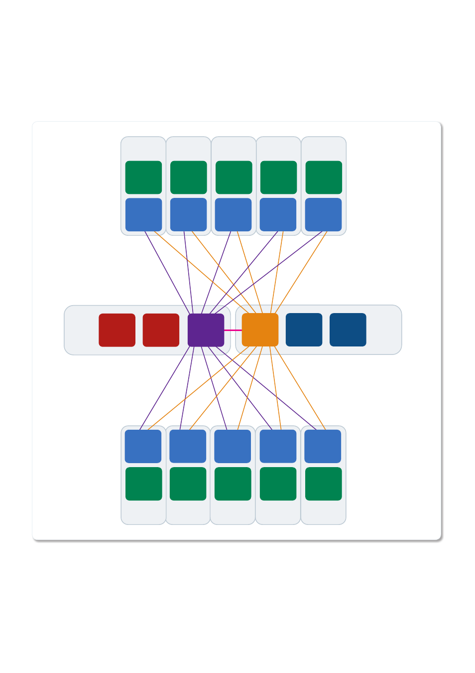
Control plane connectivity
The SwitchBlade x8100 Series control plane is facilitated by gigabit switch chips fitted to both the CFC and line cards. These provide a
gigabit connection between the CFCs, and from each CFC to each of the line card slots, as shown below:
Packet
Processor
Linecard
Slot 9
Packet
Processor
Linecard
Slot 10
Packet
Processor
Linecard
Slot 11
Packet
Processor
Linecard
Slot 12
Packet
Processor
Linecard
Slot 8
Linecard
Slot 7
Packet
Processor
Linecard
Slot 4
Packet
Processor
Linecard
Slot 3
Packet
Processor
Linecard
Slot 2
Packet
Processor
Control
Plane
Switch
Chip
1 Gbps Links
Control
Card
Slot 6
Control
Card
Slot 5
Control
Plane
Switch
Chip
Control
Plane
Switch
Chip
Control
Plane
Switch
Chip
Control
Plane
Switch
Chip
Control
Plane
Switch
Chip
Control
Plane
Switch
Chip
Control
Plane
Switch
Chip
Control
Plane
Switch
Chip
Control
Plane
Switch
Chip
Control
Plane
Switch
Chip
Control
Plane
Switch
Chip
Linecard
Slot 1
Packet
Processor
Packet
Processor
A
Packet
Processor
B
Packet
Processor
A
Packet
Processor
B
This diagram shows the control plane connectivity for the SwitchBlade x8112 12 slot chassis. The SwotchBlade x8106 6 slot chassis has
the same connectivity, but to only 4 line card slots.