3 wiring the power inputs, Wiring the power inputs – Allied Telesis AT-IMC1000TP/SFP User Manual
Page 9
Hardware Description
Wiring the Power Inputs
9
AT-IMC1000TP/SFP Industrial Gigabit PoE+ Media Converter
FIGURE 2-2 Top Panel of the Industrial Gigabit Media Converter
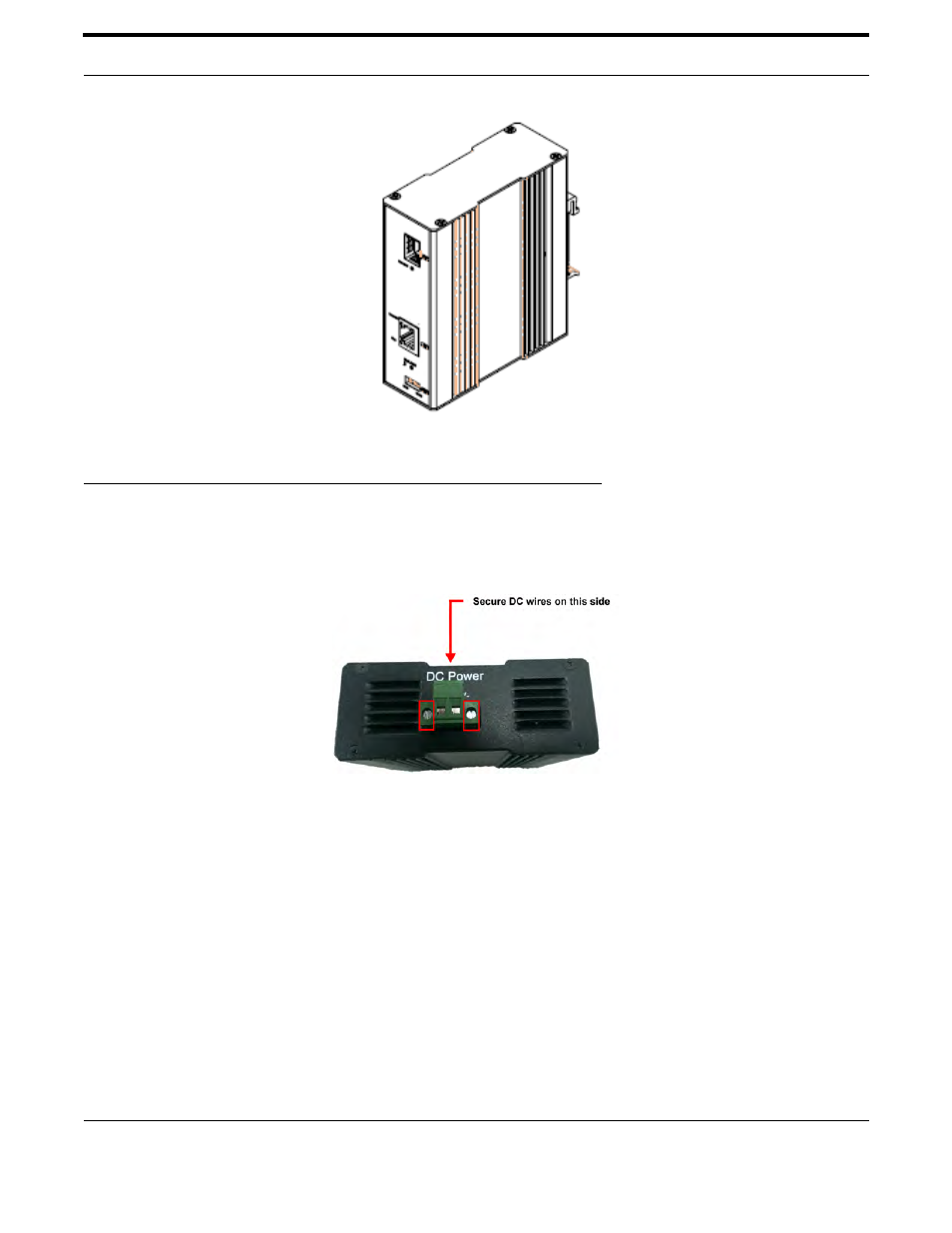
2.3 Wiring the Power Inputs
Please follow the steps below to insert the power wire.
FIGURE 2-3 Location of V+ and V- Contacts
1. There is a silk print for user to recognize the location of V+ and V- contacts on the device.
2. Insert the positive and negative wires into the V+ and V- contacts on the terminal block connector.
Note: The wire gauge for the terminal block should be in the range between 12~ 24 AWG
3. To tighten the wire-clamp screws located at the bottom of the unit (see above picture) highlighted in red for pre-
venting DC wires loosing
See also other documents in the category Allied Telesis Computer hardware:
- AT-GS908M (54 pages)
- AT-x230-10GP (80 pages)
- AT-GS950/48PS (64 pages)
- AT-GS950/10PS (386 pages)
- AT-GS950/16PS (386 pages)
- AT-GS950/48PS (386 pages)
- AT-9000 Series (258 pages)
- AT-9000 Series (1480 pages)
- IE200 Series (70 pages)
- AT-GS950/48 (60 pages)
- AT-GS950/48 (410 pages)
- AT-GS950/8 (52 pages)
- AT-GS950/48 (378 pages)
- SwitchBlade x8106 (322 pages)
- SwitchBlade x8112 (322 pages)
- SwitchBlade x8106 (240 pages)
- SwitchBlade x8112 (240 pages)
- AT-TQ Series (172 pages)
- AlliedWare Plus Operating System Version 5.4.4C (x310-26FT,x310-26FP,x310-50FT,x310-50FP) (2220 pages)
- FS970M Series (106 pages)
- 8100L Series (116 pages)
- 8100S Series (140 pages)
- x310 Series (116 pages)
- x310 Series (120 pages)
- AT-GS950/24 (404 pages)
- AT-GS950/24 (366 pages)
- AT-GS950/16 (44 pages)
- AT-GS950/16 (404 pages)
- AT-GS950/16 (364 pages)
- AT-GS950/8 (52 pages)
- AT-GS950/8 (404 pages)
- AT-GS950/8 (364 pages)
- AT-8100 Series (330 pages)
- AT-8100 Series (1962 pages)
- AT-FS970M Series (330 pages)
- AT-FS970M Series (1938 pages)
- SwitchBlade x3112 (294 pages)
- SwitchBlade x3106 (288 pages)
- SwitchBlade x3106 (260 pages)
- SwitchBlade x3112 (222 pages)
- AT-S95 CLI (AT-8000GS Series) (397 pages)
- AT-S94 CLI (AT-8000S Series) (402 pages)
- AT-IMC1000T/SFP (23 pages)
- AT-SBx3106WMB (44 pages)