4 led indicators, Led indicators – Allied Telesis AT-IMC1000TP/SFP User Manual
Page 10
Hardware Description
LED Indicators
10
AT-IMC1000TP/SFP Industrial Gigabit PoE+ Media Converter
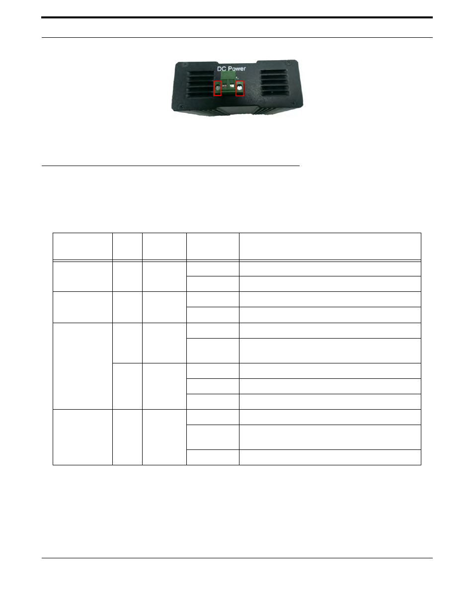
FIGURE 2-4 Securing Connector with Two Outside Screws
4. Tighten the two screws on each end of the connector to secure it to the chassis.
2.4 LED Indicators
The LEDs located on the front panel of the AT-IMC1000TP/SFP display power status and network status. Each of
them has its own specific meaning as below table.
Table 2-1: Industrial Media Converter LED Definition
LED
Indicator
Label
Color
Description
System Power
PWR
Green
On
Power on
Off
Power off
PoE Power
PoE
Green
On
PoE power input OK
Off
No PoE power input
RJ-45 (P1)
SPD
Amber
On
Link to 1000 Mbps network
Off
Not connected to network or not working at speed
of 1000M
L/A
Green
On
Connected to network
Blink
Networking is active
Off
Not connected to network
SFP (P2)
L/A
Green
On
When there is a secure SFP connection
Blink
When there is transmission or reception of data
occurring at speed of 100/1000Mbps
Off
No SFP connection detected
- AT-GS908M (54 pages)
- AT-x230-10GP (80 pages)
- AT-GS950/48PS (64 pages)
- AT-GS950/10PS (386 pages)
- AT-GS950/16PS (386 pages)
- AT-GS950/48PS (386 pages)
- AT-9000 Series (258 pages)
- AT-9000 Series (1480 pages)
- IE200 Series (70 pages)
- AT-GS950/48 (378 pages)
- AT-GS950/48 (60 pages)
- AT-GS950/48 (410 pages)
- AT-GS950/8 (52 pages)
- SwitchBlade x8106 (322 pages)
- SwitchBlade x8112 (322 pages)
- SwitchBlade x8106 (240 pages)
- SwitchBlade x8112 (240 pages)
- AT-TQ Series (172 pages)
- AlliedWare Plus Operating System Version 5.4.4C (x310-26FT,x310-26FP,x310-50FT,x310-50FP) (2220 pages)
- FS970M Series (106 pages)
- 8100L Series (116 pages)
- 8100S Series (140 pages)
- x310 Series (116 pages)
- x310 Series (120 pages)
- AT-GS950/24 (404 pages)
- AT-GS950/24 (366 pages)
- AT-GS950/16 (44 pages)
- AT-GS950/16 (404 pages)
- AT-GS950/16 (364 pages)
- AT-GS950/8 (364 pages)
- AT-GS950/8 (52 pages)
- AT-GS950/8 (404 pages)
- AT-8100 Series (330 pages)
- AT-8100 Series (1962 pages)
- AT-FS970M Series (330 pages)
- AT-FS970M Series (1938 pages)
- SwitchBlade x3106 (288 pages)
- SwitchBlade x3112 (294 pages)
- SwitchBlade x3106 (260 pages)
- SwitchBlade x3112 (222 pages)
- AT-S95 CLI (AT-8000GS Series) (397 pages)
- AT-S94 CLI (AT-8000S Series) (402 pages)
- AT-IMC1000T/SFP (23 pages)
- AT-SBx3106WMB (44 pages)