AFX NXL220SS User Manual
Nxl series, Assembly instructions, Line voltage xenon undercabinet fixtures
NXL SERIES
Line Voltage Xenon Undercabinet Fixtures
Models 120, 220, 320, 420, & 520
Interconnectable / Cord or Direct Wire
Page 1 of 2
8060611 Rev3
Safety Precautions
Read all safety precautions and installation instructions carefully
before installing or servicing this fixture. Failure to comply with
these instructions could result in potentially fatal electric shock
and/or property damage.
It is recommended that a qualified electrician perform all wiring. This
fixture must be wired in accordance with all national and local
electrical codes.
Do not handle an energized fixture or attempt to energize any fixture
with wet hands or while standing on a wet or damp surface or in
water.
Make sure that the power source conforms to the requirements of the
fixture. (See labels on fixture housing).
To reduce the risk of electrical shock, and to assure proper operation,
this fixture must be adequately grounded.
Lighted lamp is HOT!
Bulb gets HOT quickly! Do not touch hot lens or enclosure.
Do not touch bare lamp with your bare skin. Oils from
your skin may damage the lamp when it heats up.
12-inch minimum spacing distance from glass required
for all objects located under fixture.
For NXL Series Model No’s::
Do not interconnect more than 560 watts
Example: 560 watts (28 lamps x 20w)
Use only a 120V/20W or smaller Xenon bulb (bi-pin Base Only).
This fixture is to be used for general indoor lighting in dry locations
only.
Dimming: This unit can be dimmed with a standard incandescent
wall dimmer.
Assembly Instructions
1. Preparation for Installation
A. Disconnect electrical power before installing or servicing
any part of this fixture.
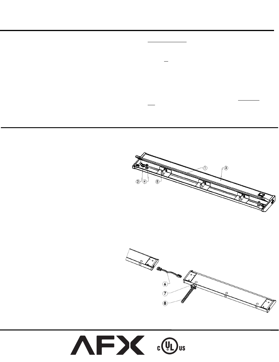
B. Place fixture on a clean flat surface with lens (1) towards
you.
C. Open (1) glass lens by lifting both hinge tabs at each end
D. If (5) lamps are not installed and packed separately,
carefully put aside for later use. (DO NOT TOUCH LAMP
glass with bare hands, oils from your skin may damage
lamp when it heats up.)
E. Determine input power method (Hardwire, Cord or Link)
below and follow corresponding directions.
2.
Cord to Outlet Installation
(Skip this step if using Hardwire or Link to Fixture
Installation)
A. Fixture must be mounted within 5’ of an outlet. Locate the 5’ power cord included in the box.
B. Connect Cord to fixture by snapping the quick connect end of the cord to the corresponding connector in the end of the fixture marked “IN”. The
cord will only connect to the “IN” connector so make sure you have the right connector identified. Do not force the connection, it should snap in
easily.
C. Follow the directions for Mounting and Lamping below.
D. Once Mounting and Lamping are completed, plug the
cord into the outlet.
3.
Hardwire Installation Preparation
(Skip this step if using Cord to Outlet or Link to
Fixture Installation to Power Unit)
A. Discard Cord if Hardwire Installation is used.
B. Open cover (3) by squeezing to disengage it from the (2)
retaining tabs of the housing. Rotate it 90º.
C. Remove the ½” diameter knock-out for supply wiring
entry.
D.
Determine appropriate cable and mounting parts:
i)
Cable connector (7) is included.
ii) BX(AC) 3/8” trade size cable (8) (not included).
iii) Anti-short bushing (not included).
E. Insert the cable connector into the housing open hole.
Secure it with the nut.