AFX EXD220WH User Manual
Exd series, Assembly instructions, Line voltage xenon undercabinet fixture
EXD SERIES
Line Voltage Xenon Undercabinet Fixture
Models 120, 220, 320, & 420
Direct Wire
Page 1 of 2 8060524 R5
Safety Precautions
Read all safety precautions and installation instructions carefully
before installing or servicing this fixture. Failure to comply with
these instructions could result in potentially fatal electric shock
and/or property damage.
It is recommended that a qualified electrician perform all wiring. This
fixture must be wired in accordance with all national and local
electrical codes.
Do not handle an energized fixture or attempt to energize any fixture
with wet hands or while standing on a wet or damp surface or in
water.
Make sure that the power source conforms to the requirements of the
fixture. (See labels on fixture housing).
To reduce the risk of electrical shock, and to assure proper operation,
this fixture must be adequately grounded.
Lighted lamp is HOT!
Bulb gets HOT quickly! Do not touch hot lens or enclosure.
Do not touch bare lamp with your bare skin. Oils from
your skin may damage the lamp when it heats up.
12-inch minimum spacing distance from glass required
for all objects located under fixture.
Use only a 120V/20W or smaller Xenon bulb (bi-pin Base Only).
This fixture is to be used for general indoor lighting in dry locations
only.
Dimming: This unit can be dimmed with a standard incandescent
wall dimmer.
Assembly Instructions
1. Preparation for Installation
A. Disconnect electrical power before installing or servicing any part of
this fixture.
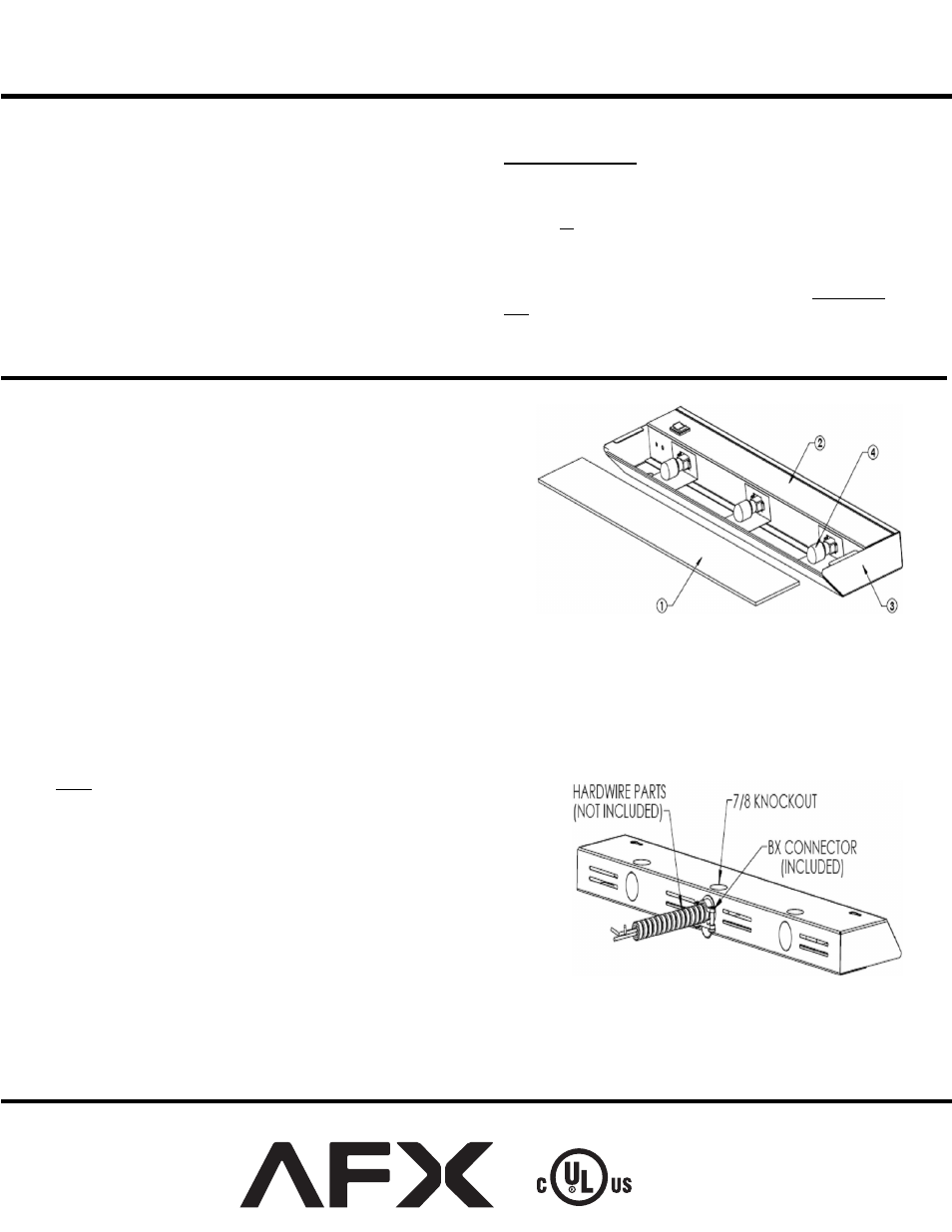
B. Place fixture on a clean flat surface with lens (1) towards you.
C. Remove glass lens by lightly pressing down on both ends while sliding it
directly away from the fixture.
D. If lamps are not installed and packed separately, carefully put aside for
later use. (DO NOT TOUCH LAMP glass with bare hands, oils from
your skin may damage lamp when it heats up.)
2. Hardwire Installation Preparation
A. Open cover by squeezing to disengage it from the retaining tabs of the
housing. Rotate it 90º.
B. Remove appropriate 7/8” diameter knockout for supply wiring entry.
C.
Determine appropriate connector:
i)
NM-Romex - A non-metallic push-on connector is included for use.
ii) Flexible conduit (BX)– A push-on connector (shown) is included for use.
D. Insert BX cable (not included) or Romex (not included) through appropriate connector.
Feed appropriate supply wires (1 black wire, 1 white wire and a ground wire) through
open 7/8” hole in the housing and push connector into hole until it snaps in place.
Note:
Injury to persons and damage to the mounting surface may result if the fixture or
mounting hardware is pulled from the mounting location. To reduce the possibility of
such injury, be sure to mount the fixture only on a surface that is mechanically,
structurally sound.
3. Mounting
A. Using keyhole slots for mounting the fixture. Position the housing in location
intended for mounting. Mark mounting screw location by using keyhole slots
as guides. Remove housing and partially install both #8 x ½” wood screws
(provided) in the marked positions. Mount the housing to desired surface by
placing the keyhole slots over mounting screw and shifting housing to one side
to secure in position. Tighten mounting screws.
DIRECT WIRE WITH
ONE FIXTURE