Czpc series, Cable mounted pendants – AFX CZPC425KBSCTD-WHWH User Manual
Page 2
CZPC Series
Cable Mounted Pendants
Page 2 of 3 8060684 R0
3.
Fixture mounting from Junction Box (Fig 1).
A.
Install the short screws (1) with lock washers (3) and hex nuts (4) all provided into the offset holes (2) of the round mounting
bracket as shown in Fig 1. Be sure these two screws (1) line up with holes in canopy (6) and point away from junction box.
Note: These short screws (1) may require adjustment to mount the two ball nuts (7) correctly.
B.
Install and secure the round mounting bracket assembly to the junction box (not provided) in ceiling with the longer screws
(5) provided.
4.
Wiring Canopy Cord Assembly to Junction Box.
Caution: Make sure power is off at fuse or circuit breaker box. Check power wires for damage or scrapes. If power supply wires are
within three inches of ballast use wire suitable for at least 90C (194F). Note: Most dwellings built before 1985 have supply wire rated
to 60C. Consult a qualified electrician before installing.
A.
Attach (one of the wire in Fig 3) the cord no color wire (13) to the in-coming supply ground wire.
B.
Models ending in MV: Using luminaire disconnect provided, insert white supply wire into the hole across from white ballast
lead. Insert black hot supply wire into hole across from black ballast lead. Do not mix wires.
C.
Models ending in SCTD: Use wire connectors provided to connect in-coming white supply wire to cord white wire. Connect
in-coming black supply wire to cord black wire. Do not mix wires.
D.
Pull on each wire to make sure connections are secure. Make certain no bare wires are exposed outside of wire connectors.
E.
Line up the two holes in the canopy (6) with the two screws in the round mounting bracket. Secure fixture to screws with the
two thumb ball nuts (7) provided.
5.
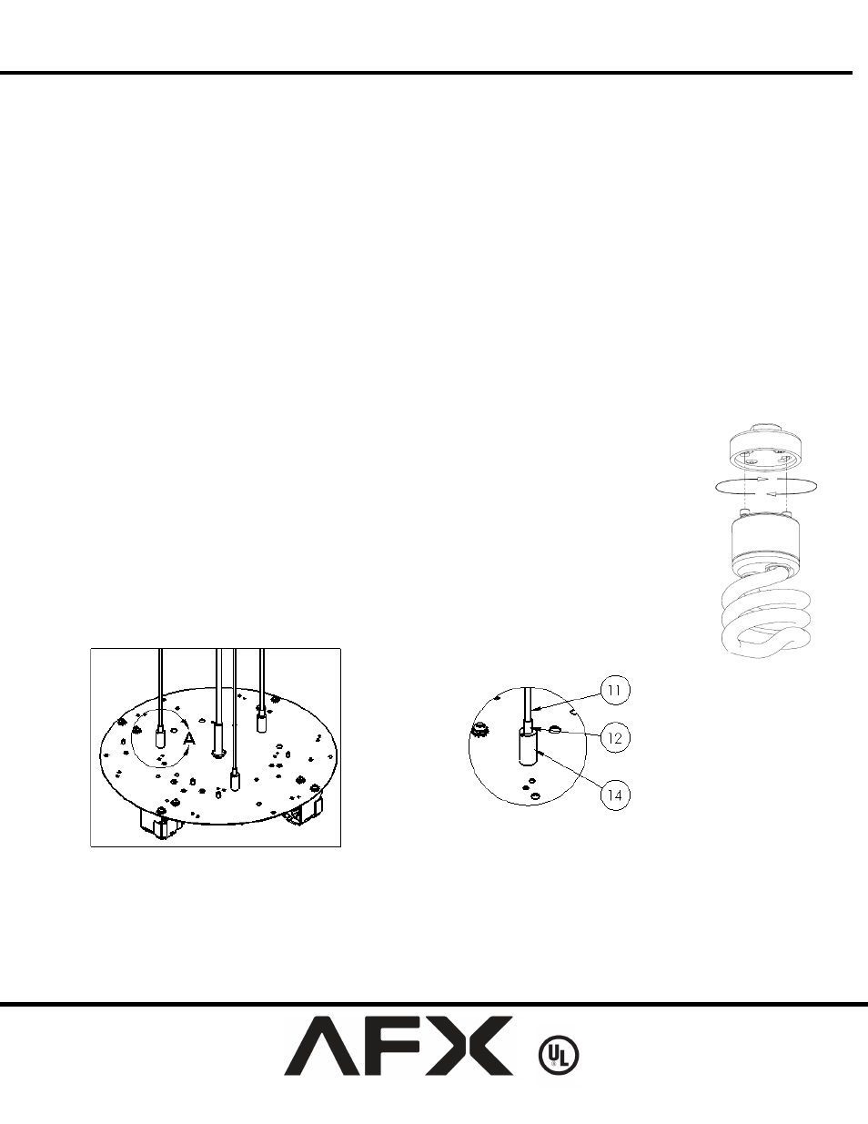
Aircraft Cable Adjustments.
A.
Adjust the aircraft cables up and down by pressing the “Spring Pin” (12) Fig 5 downward and holding
until the proper cable length is attained and repeat the same steps to the other two cable assemblies.
Note: Extra cable length should be looped, tied, or cut to minimize lamp shadows.
6.
Lamp Installation (Lamps included on models ending with “SCTD”).
A.
For models ending in MV, use only 18W/26W (max) fluorescent, quad 4-pin lamps (9). To install, line-
up lamp pins with the corresponding holes in the lamp socket and push lamp into place until a click is
heard. Repeat for each lamp.
B.
Models ending in SCT use a GU24 base lamp 18W/26W (max). To install, line up lamp pins with the
corresponding holes in lamp socket and turn clockwise until a click is heard Fig 4. Repeat for each lamp.
NOTE: BE CAREFUL NOT TO ROTATE PENDANT DURING LAMP
INSTALLATION/REPLACEMENT
FIG 5
FIG 4