AFX LW217WAR8 User Manual
Page 2
INSTALLATION INSTRUCTIONS
1
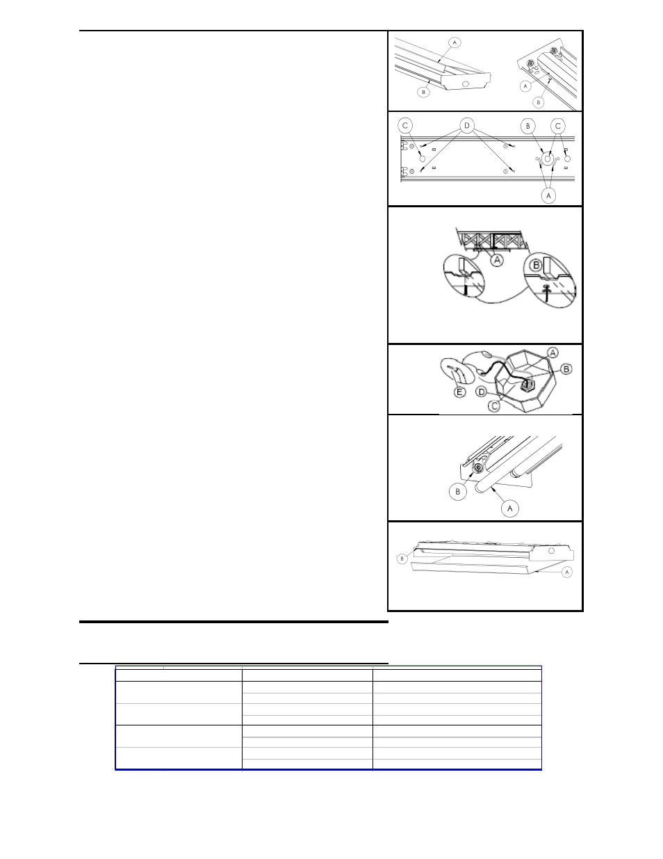
Separate the diffuser (Fig. 1-A) from the fixture body (FIG. 1-
B) by shifting it to one side and pulling it from assembly.
2
Separate the ballast cover from the fixture body by squeezing
it in at dimples (Fig. 2-B) and pulling it from the assembly.
(Fig. 2-A).
3
For models with wood ends – Open two small knockouts in
each metal end cap and attach wood with wood screws
provided into predrilled holes in wood ends.
4
Remove appropriate mounting knockouts (Fig.3-D). Four
located on each side of channel. Determine and remove the
appropriate knockout for power supply wires in channel ( Fig.
3 B or C) or in endcap.
5
Lift fixture up and capture one or more screws in junction box
into the screw retention yoke (Fig. 3-A) until it is captured and
can not be slid back out. Mark the locations of the eight 1/4”
diameter-mounting holes (Fig. 3-D) on the ceiling.
4
Take the channel down and locate the ceiling joists with a
stud finder or punch a small hole into the ceiling at each
location using a nail or an awl to see if there is a wood joist. If
there is a joist use a suitable wood screw (not included) (Fig.4-
A) to mount the channel. Where there is no joist to screw into
use a ¼” toggle bolt (not included) (Fig.4-B) of suitable length
to mount channel securely to the ceiling.
5
Pull the supply power wires from junction box (Fig 5) or power
supply through the appropriate knockout hole into the fixture.
Secure fixture to ceiling with appropriate mounting hardware
(Fig. 4 A or B). The screw captured in the screw retention
yoke can be tightened to prevent fixture vibration.
Fig. 3
Fig. 1
Fig. 4
Fig. 2
Fig. 5
yoke can be tightened to prevent fixture vibration.
6
Use wire nut to connect white wire from ballast to neutral
supply wire. (Fig. 5-A) Strip supply wires if needed. (Fig. 5-E)
Use wire nut to connect black wire from ballast to power
supply wire. (Fig. 5-B) Cover wire nuts and connections
completely in electrical tape. Secure bare or green ground
wire to green screw in the channel.
7
Place ballast cover (Fig. 2-A) onto fixture. Squeeze cover and
attach under dimples. (Fig. 2-B) DO NOT PINCH WIRES.
8
Install lamps into fixture. (Fig. 6-A) Each lamp has 2 pins on
each end. Align the pins with slots in socket (Fig. 6-B) and
slide lamp into place. When all 4 pins are in place, rotate
lamp 90°.
9
Place diffuser (Fig. 7-A) onto fixture. Hang long side onto
channel body (Fig. 7-B), swing diffuser up to clear other side
and shift to center.
CARE AND MAINTAINENCE
Periodically, dust the diffuser (inside and out) with a clean, dry cloth. Wipe clean with a slightly damp cloth as needed. Never use
TROUBLESHOOTING
Fig. 6
Fig. 7
Possible Cause
Corrective Action
1. Fixture wiring problem.
1. Check wiring for loose connections.
2. No power or failed switch.
2. Check power and switch.
3. Worn-out lamp(s).
3. Replace lamp(s) as needed.
4. Failed ballast.
4. Replace ballast as needed.
1. Fixture not properly grounded.
1. Check grounding system.
2. Wrong lamp(s).
2. Verify lamp is listed on ballast.
3. One or more failing lamps.
3. Replace lamps as needed.
4. Failing ballast.
4. Replace ballast as needed.
lights ends only.
Problem
Light fails to illuminate.
No flickering.
Light flickers blinks or
2.