AFX ADLF432SNR8 User Manual
Page 3
4
5
ASSEMBLY INSTRUCTIONS
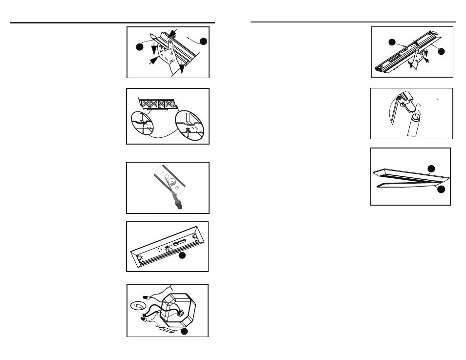
3. Separate the ballast cover (E) from the fixture
body (A) by squeezing it in at dimples and pulling
it from the assembly. (See Figure 3).
Figure 3
E
A
4.
Locate the ceiling joists with the stud finder.
Hold fixture body (A) in place and mark the holes.
Drill 1/4 in holes through celiling boards for toggle
bolts (not included) if needed. Be sure that the
supply wires can pass directly into the fixture
body (A). (See Figure 4).
NOTE: When mounted, the mounting hardware
must secure the fixture solidly to the ceiling.
Screws (not included) must penetrate joists
or toggle bolts (not included) must be placed
through the ceiling boards.
Figure 4
5. Remove the appropriate knockout nearest the
power supply wires. Protect wires passing through
hole with snap in brushing (not included).
(See Figure 5).
Figure 5
6. Mount the fixture with appropriate mounting
hardware (not included) while passing the power
supply wire, the supply neutral wire and the supply
groundwire from junction box or power supply
through the appropriate knockout hole into the
fixture body (A). (See Figure 6).
Figure 6
A
7.
Use wire nut (not included) to connect white
wire from ballast (F) to neutral supply wire. Strip
supply wires if needed. Use wire nut
(not included) to connect black wire from ballast
(F) to power supply wire. Cover wire nuts and
connections completely in electrical tape. Secure
bare or green ground wire to green screw in the
channel of fixture body (A).
(See Figure 7).
Figure 7
F
ASSEMBLY INSTRUCTIONS
8. Place ballast cover (E) onto fixture body (A).
Squeeze cover and attach under dimples.
DO NOT PINCH WIRES. (See Figure 8).
Figure 8
A
E
9.
Install (4) 32-watt T8 bulbs (not included) into
fixture. Each bulb has 2 pins on each end. Align
the pins with slots and slide bulbs into place.
When all 4 pins are in place, rotate 90°.
(See Figure 9).
Figure 9
ROTATE 90
10. Install diffuser (C) by sliding one corner
of the lens into a corner of the frame (B) until
the short end of the diffuser is totally inside of
the frame. Slide the diffuser into the frame
until the other end of the lens clears the inside
edge of the frame. Lower the diffuser so that it
rests into the bottom of the Frame and adjust
if needed. (See Figure 10).
Power to the fixture can now be restored.
Figure 10
B
C