Caution, Fig. 15 shows a typical heat/cool wiring schematic – AMX ViewStat User Manual
Page 28
ViewStat Installation and Wiring
22
ViewStat Communicating Thermostat
b.
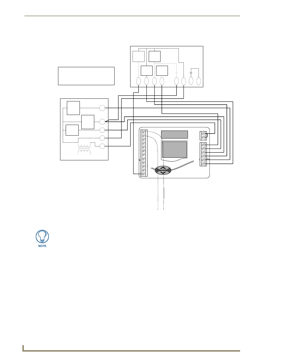
FIG. 15 shows a typical heat/cool wiring schematic:
FIG. 15
Typical heat pump wiring schematic
RC
RH
Y1
W1
G
O
W2
C
RSC
RSA
RSB
RSR
R
REF
Y2
B-
B+
A+
A-
B
CAUTION!
ENSURE HVAC SYSTEM POWER
IS OFF BEFORE WIRING
USE 18-20 GA. THERMOSTAT CABLE. NUMBER
OF CONDUCTORS REQUIRED DEPENDS ON THE
HVAC SYSTEM BEING CONTROLLED
REFER TO THE THERMOSTAT INSTALLATION
SHEET FOR INTERNAL SCHEMATIC, THERMOSTAT
CHECK-OUT PROCEDURES AND OTHER HVAC
WIRING DETAILS
FAN
RELAY
2ND
STAGE
AUX.
HEAT
1ST
STAGE
AUX.
HEAT
R
INDOOR BLOWER/HEAT
UNIT
C
G
W1
W2
L1
L2
120
VAC
24
VAC
Y1
O
B
W1
L
C
R
1ST
STG
COMP.
REV
VALVE
COOL
REV
VALVE
HEAT
DE
F
R
OS
T
SER
VI
C
E
OUTDOOR HEAT PUMP UNIT
Y2
2ND
STG
COMP.
(from MiniVerter)
Black
(common)
Red
(power)
For additional HVAC system wiring diagrams (for Single-Stage Furnace and AC,
Two-Stage Furnace and Two-Stage AC, Roof-Top Unit (Two-Stage Heat and Two-
Stage Cool), Boiler With AC (Two Transformers), and Single Stage Heat Pump
Configurations, refer to the Wiring Diagrams section on page 26.