Wiring the thermostat – AMX ViewStat User Manual
Page 26
ViewStat Installation and Wiring
20
ViewStat Communicating Thermostat
Wiring the Thermostat
1.
Strip 1/4" (0.63 cm) of insulation from each wire to be used.
2.
Secure wires into the terminals on the base according to the appropriate wiring diagram, as described in
the following table. Refer to the Wiring Diagrams section on page 26. Use color-coding practices (i.e.
white wire to W terminal) whenever possible.
3.
Check each wire to ensure it is securely fastened, not broken, and exposed wires are not touching.
Communication and Equipment terminal wiring definitions
The following table describes the Communication and Equipment terminal wiring definitions (see FIG. 5 on
page 10).
• Single Stage Furnace & AC
Refer to FIG. 18 on page 26
• Two Stage Furnace & Two Stage AC
Refer to FIG. 19 on page 27
• Roof Top Unit (Two Stage Heat & Two Stage Cool) Refer to FIG. 20 on page 28
• Boiler with AC (Two Transformers)
Refer to FIG. 21 on page 29
• Single Stage Heat Pump
Refer to FIG. 22 on page 30
• Two Stage Heat Pump
Refer to FIG. 23 on page 31
• First Stage Radiant Floor Heat
Second Stage Furnace One Stage of Cooling
Refer to FIG. 24 on page 32
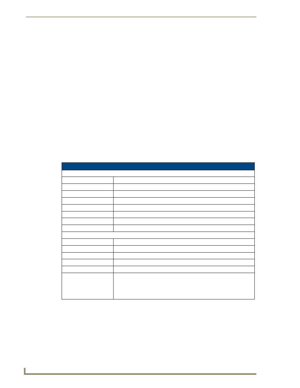
Communication and Equipment Terminal Wiring Definitions
Communication Terminal
C
Thermostat Voltage (common)
R
Thermostat Voltage (hot)
RSR (support module)
Thermostat Voltage (hot)
RSC (support module)
Thermostat Voltage (common)
RSB/RSA (support module) Support module communication (half-duplex)
REF
Ground Reference
B-/B+
Receive
A-/A+
Transmit
Equipment Terminal
RC
Switched Voltage (cool)
RH
Switched Voltage (heat)
RV COOL (O)
Reversing Valve - Cool (energized in Cool mode)
RV HEAT (B)
Reversing Valve - Heat (energized in other modes)
G
Fan
HUM/W1
1st stage Heat (non-heat pump)
-or-
3rd stage Heat AND 1st Stage Emergency Heat (heat pump)
-or-
Humidification (with humidity control sensor)