Connecting the viewstat to the hvac system, Caution, Connecting the viewstat to the hvac system 1 – AMX ViewStat User Manual
Page 27: Make sure the hvac system power is off
ViewStat Installation and Wiring
21
ViewStat Communicating Thermostat
Connecting the ViewStat to the HVAC System
1.
Make sure the HVAC system power is off.
2.
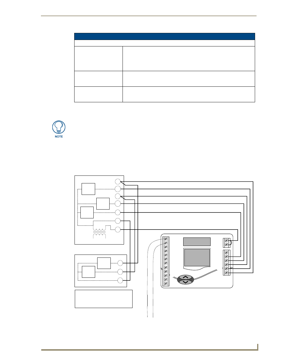
The following figures (FIG. 14, FIG. 15) show wiring diagrams for several different HVAC equipment
types. Use these diagrams as a reference only. Use color coding where possible.
a.
FIG. 14 shows a typical heat/cool wiring schematic:
Communication and Equipment Terminal Wiring Definitions (Cont.)
Equipment Terminal (Cont.)
DEH/Y1
1st stage Cooling (non-heat pump)
-or-
1st stage Compressor (heat pump)
-or-
Dehumidification (with humidity control sensor)
W2
2nd stage Heat (non-heat pump)
-or-
2nd stage Emergency Heat (heat pump)
Y2
2nd stage Cooling (non-heat pump)
-or-
2nd stage Compressor (heat pump)
A qualified HVAC technician should perform these steps step to ensure proper
termination.
FIG. 14
Typical heat/cool wiring schematic
RC
RH
Y1
W1
G
O
W2
C
RSC
RSA
RSB
RSR
R
REF
Y2
B-
B+
A+
A-
B
FAN
RELAY
2ND
STAGE
HEAT
1ST
STAGE
HEAT
R
MULTI-STAGE FURNACE
C
G
W1
Y1
W2
Y2
1ST STAGE
COOL
2ND STAGE
COOL
L1
L2
120
VAC
24
VAC
1ST
STG
COOL
2ND
STG
COOL
MULTI-STAGE A/C
Y1
C
Y2
CAUTION!
ENSURE HVAC SYSTEM POWER
IS OFF BEFORE WIRING
USE 18-20 GA. THERMOSTAT CABLE. NUMBER OF CONDUCTORS
REQUIRED DEPENDS ON THE HVAC SYSTEM BEING CONTROLLED
REFER TO THE THERMOSTAT INSTALLATION SHEET FOR
INTERNAL SCHEMATIC, THERMOSTAT CHECK-OUT
PROCEDURES AND OTHER HVAC WIRING DETAILS
(from MiniVerter)
Black
(common)
Red
(power)