Overview, Link analysis, How far can you go – Campbell Scientific RF401-series and RF430-series Spread Spectrum Data Radios/Modems User Manual
Page 84
Appendix H. Distance vs. Antenna Gain, Terrain, and Other Factors
theoretically extends the attainable distance by a factor of 2.8. Adding 9 dBd
yagi antennas on both ends in place of 0 dBd whip antennas theoretically
extends the distance by a factor of 7.9. The higher the yagi’s gain, the
narrower the beam width and the more critical it is that it be aimed right on
target.
How Far Can You Go?
Distance Estimates for Spread Spectrum Radios
Overview
There is a great deal of interest in estimating the distance you can expect to
achieve with the RF401 radios. Also of interest are the effects of cable length,
antenna gain, and terrain. Some of these items are easy to quantify (cable loss,
for instance); others are difficult to quantify (such as the effect of ground
reflections). They are all important, though, and affect how well the RF system
performs.
Probably the best approach to take in making range estimates is to do a site
survey that considers the topography, location of antennas and radios, and
cable lengths, make some assumptions about the path losses, and see if there is
still some net gain. If there is, or if it is close, the next course is to actually try
it out.
Link Analysis
In an RF system, there are gains (transmitter power, antenna gains, and
receiver sensitivity “gain”) and losses (cable loss and path loss). If the gains
exceed the losses, you have a connection; any excess is the “link margin”.
Parenthetical values pertain to 2.4 GHZ
EXAMPLE GAINS
EXAMPLE LOSSES
Transmitter Power 20 (17)
Transmitter Cable
3
Transmitter Antenna 6
Free Space
120
Receiver Antenna
6
Receiver Cable
3
Receiver Sensitivity “gain”
110 (104)
TOTAL GAINS =142 (133) dB TOTAL LOSSES =
126 dB
Link Margin = (Total Gains) – (Total Losses) = 142 (133) – 126 = 16
(7) dB
A minimum of 6 dB of link margin is recommended.
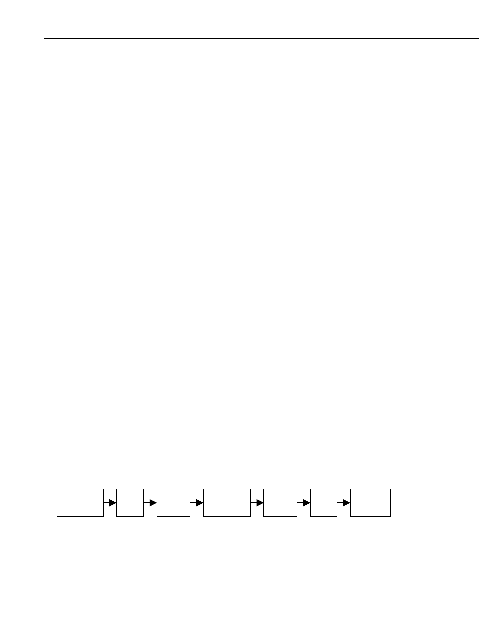
Here is a block diagram of the various components of gain/loss:
Cable
Loss
Antenna
Gain
Free Space
Loss
Antenna
Gain
Cable
Loss
Radio
Receiver
Radio
Transmitter
Pt - Lt + Gt - Lp + Gr - Lr = Pr
H-2