2 step 2 – set up remote rf401, Step 2 – set up remote rf401, 1. rf401 basic point-to-point network – Campbell Scientific RF401-series and RF430-series Spread Spectrum Data Radios/Modems User Manual
Page 21
RF401-series and RF430-series Spread Spectrum Radio/Modems
- RX LED Test -
To determine if there is a neighboring radio network in operation
using the same hopping sequence as yours, stop communications on
your network and observe your radio’s green LED for activity. A
flashing green LED would indicate that there is a nearby network
using the same hopping sequence.
•
Click apply after changing settings.
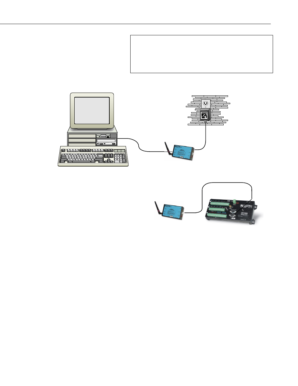
FIGURE 3-1. RF401 Basic Point-to-Point Network
3.2.2 Step 2 – Set Up Remote RF401
a. Connect an antenna (or antenna cable with Yagi or omnidirectional
antenna attached) to the RF401 antenna jack. The separation between the
base RF401 antenna and the remote RF401 antenna can be any convenient
distance (see Sections 3.3, Antenna Considerations, and 4.4, Compatible
Antennas).
b. Use the SC12 serial cable to connect the datalogger CS I/O port to the
remote RF401 radio’s CS I/O port. The CS I/O port on newer dataloggers
applies power to the remote RF401.
With older dataloggers lacking 12 V on pin 8 (see TABLE 3-2), you can
power the RF401 using a Field Power Cable (see above hardware list)
between the datalogger’s 12 V (output) terminals and the RF401’s
“Power” jack.
LoggerNet
AC Adapter
RS-232
CS I/O
Datalogger CS I/O
9