At the datalogger, At the am16/32b – Campbell Scientific AM16/32B Relay Multiplexer User Manual
Page 41
AM16/32B Relay Analog Multiplexer
COM EVEN H
COM EVEN L
EVEN H
EVEN L
SENSOR SHIELDS
COM
"4 X 16" Mode
COM ODD H
COM ODD L
CU
CO
CU
CO
ODD H
ODD L
CU
CO
CU
CO
/
0
21X/
CR7
CR10(X)
CR2
CR3000/
CR800/CR850/
3X/CR1000/
CR5000
H H
H
L L
H H
L L
L
H
L
G
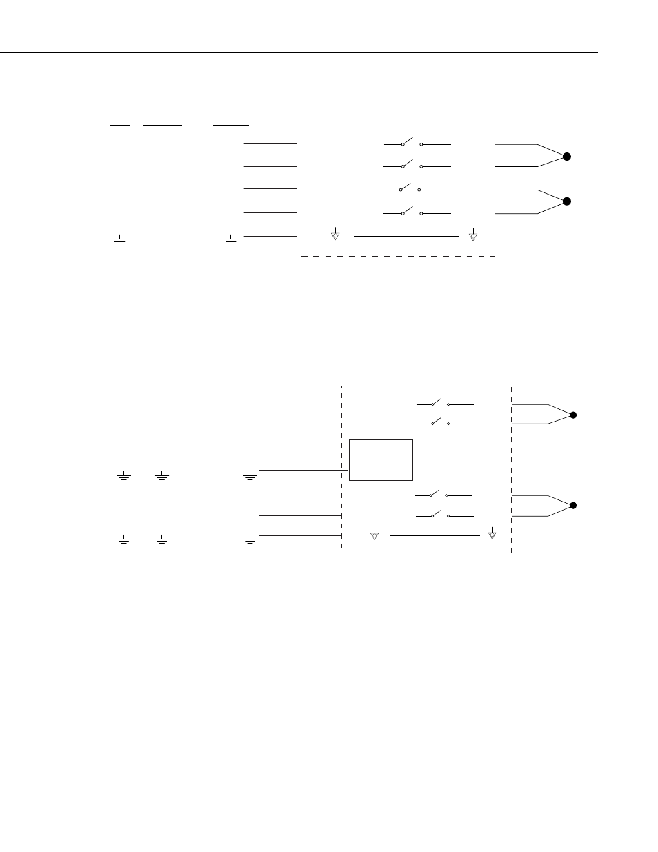
FIGURE 6-8. Differential thermocouple measurement with reference
junction at the datalogger
COM EVEN H
COM EVEN L
EVEN H
EVEN L
SENSOR SHIELDS
COM
"4 X 16" Mode
COM ODD H
COM ODD L
107
ODD H
ODD L
CU
CO
CU
CO
CU
CU
CU
CU
/
0
CR23X/
CR800/
CR850/
CR1000
21X/
CR7
CR10(X)
CR3000/
CR5000
H
H H H
L L L
EX E E
H H H
L
VX
H
AG
H H H
L L L
H
L
G
ence
If a mix of TCs and other sensor types are multiplexed through the AM16/32B,
it is generally best to locate the reference junction on the AM16/32B, as shown
in FIGURE 6-9.
AM16/32B Reference — An external reference, usually a thermistor, can be
located at the AM16/32B, as shown in FIGURE 6-9. This approach requires
an additional single-ended datalogger input to measure the reference. Position
the reference next to the COM terminals and, when practical, measure the
thermocouples on SETs that are in close proximity to the COM terminals in
order to minimize thermal gradients.
FIGURE 6-9. Differential thermocouple measurement with refer
junction at the AM16/32B
31