1 com terminals, 2 sensor input terminals, Com terminals – Campbell Scientific AM16/32B Relay Multiplexer User Manual
Page 21: Sensor input terminals, Using cable4cbl cable, Figure 4-4), 1 com termin, 2 sensor inpu, T terminals, Am16/32b relay multiplexer
AM16/32B Relay Multiplexer
4.2.1 COM Termin
ue COM next to the mode switch. The terminals are labeled: ODD
s
als
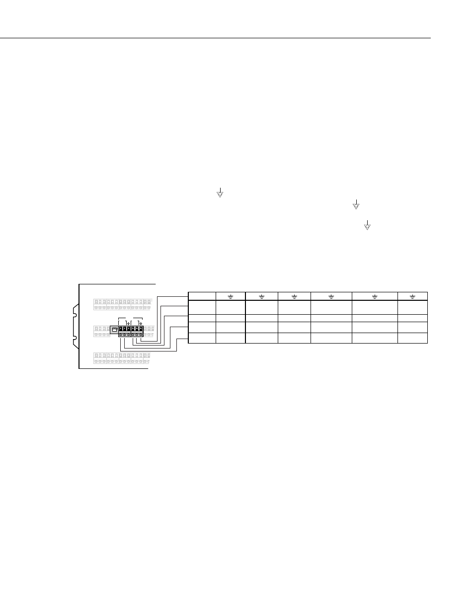
A CABLE3CBL, CABLE4CBL, or CABLE5CBL cable is used to connect the
datalogger to the COM terminals. The CABLE3CBL is recommended when
the AM16/32B is used in the 4x16 mode. The CABLE4CBL is typically used
for the 4x16 mode. The CABLE5CBL is recommended for the 4x16 mode
when it is desirable to connect both shields.
The four terminals dedicated to multiplexer-datalogger connection are located
under the bl
H, ODD L, EVEN H, and EVEN L. In “4x16” mode the AM16/32B maintain
the four COM terminals electrically isolated from one another. In “2x32”
mode, the AM16/32B maintains an internal connection between ODD H and
EVEN H and between ODD L and EVEN L.
Common “
” terminals are provided next to the COM ODD and COM EVEN
terminals. They bus internally to the
other thirty-two “ ” terminals on the
AM16/32B and are connected at all times (not switche
Their function is to
provide a path to ground for sensor cable shields. A C
d).
OM
terminal should
be wired to datalogger ground via the cable’s shield according to the following
table.
COM
ODD
4X16
H
L
EVEN
H
L
O
N
MUXSIGNAL
SHIELD
CR10X
CR23X
CR1000
CR3000,
CR5000
21X
CR7
CR800,
CR850
G
CABLE
E1-E3 EX1-EX4
EX1-EX3
or
VX1-VX3
VX1-VX4 EXCITATION SWITCHED
ANALOG OUT
EX1-EX2 or
VX1-VX2
SE3 SE3 SE3 SE3
2H
2H
SE3
SE2 SE2 SE2 SE2
1L
SE2
1L
SE1 SE1 SE1 SE1
1H
1H
SE1
FIGURE 4-4. Typical AM16/32B to datalogger signal hookup (4x16
mode) using CABLE4CBL cable
4.2.2 Sensor Inpu
In “4x16” mode, the odd numbered terminals (example: 5H, 5L) are relay
switched to the COM ODD terminals while the even terminals (6H, 6L) are
switched to the COM EVEN terminals. When activated by the RES line being
high, as the AM16/32B receives clock pulses from the datalogger, each SET of
four in turn is switched into contact with the four COM terminals. For
example, when the first clock pulse is received from the datalogger, SET 1
t Terminals
The terminals for sensor attachment are divided into 16 groups (panel switch
set to “4x16”) or into 32 groups (panel switch set to “2x32”). The groups
consist of four or two Simultaneously Enabled Terminals (SETs). With panel
switch set to “4x16” mode, the blue channel numbers apply. The SETs are
numbered starting at 1 (1H, 1L, 2H, 2L) and continuing until SET 16 (31H,
31L, 32H, 32L).
11