2 measurement terminals, Measurement terminals – Campbell Scientific AM16/32B Relay Multiplexer User Manual
Page 20
AM16/32B Relay Multiplexer
The average power required to operate an AM16/32B depends on the
percentage of time it is active per time period. For example, if a CR10X makes
differential measurements on 32 thermocouples every minute, the average
current drain due to the AM16/32B would be about ((.030 s/chan x 32 chan)/
60 s) x 6 mA = 0.1 mA. Under the same conditions, a 2-second execution
interval rate increases the average system current drain to about ((.030 s/chan x
32 chan)/2 s) x 6 mA = 2.9 mA. At a minimum, the power supply must be able
to sustain the system between site visits anticipating the worst environmental
extremes.
If a 21X power supply is used to power the AM16/32B, all low-level analog
measurements (thermocouples, pyranometers, thermopiles, etc.) must be made
differentially. Differential measurements are required because slight ground
potentials are created along the 21X analog terminal strip when the 12V supply
is used to power peripherals. This limitation reduces the number of available
analog input channels and may mandate the use of an external power supply
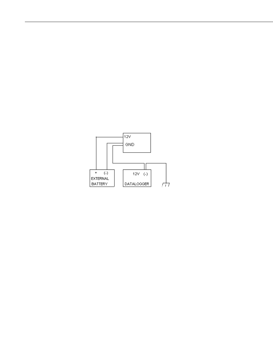
for the AM16/32B (FIGURE 4-3).
FIGURE 4-3. Power and ground connections for external power supply
Low supply voltage and high ambient temperatures affect the actuation time of
the multiplexer relays (FIGURE 3-1). If your program does not allow the relay
contacts sufficient time to close before a measurement is started, the result will
be inaccurate or overranged values.
4.2 Measurement Terminals
Most of the terminals on the AM16/32B are dedicated to the connection of
sensors to the multiplexer (FIGURE 2-1). Depending on the panel switch
selection (“4x16” or “2x32” mode), the sensor input terminals are organized
into 16 groups (blue letters) of 4 sensor inputs or 32 groups (white letters) of 2
sensor inputs. The terminals accept solid or tinned, stripped sensor leads. The
four COM terminals marked ODD H, L and EVEN H, L located by the mode
switch provide for attachment of the common signal leads that carry
multiplexed sensor signals to the datalogger.
AM16/32B
10