2 potentiometer measurement, Potentiometer measurement, Cable) – Campbell Scientific AM16/32B Relay Multiplexer User Manual
Page 37
AM16/32B Relay Analog Multiplexer
/
0
"4 X 16" Mode
COM H (ODD)
COM L
COM H (EVEN)
COM L
ODD H
ODD L
EVEN H
EVEN L
SHIELD
SENSOR SHIELDS
COM
MUXSIGNAL
SHIELD
CR23X/
CR800/
CR850/
CR1000
21X/
CR7
CR10(X)
CR3000/
CR5000
VX
EX E E
L L L
H H H H
L
AG
G
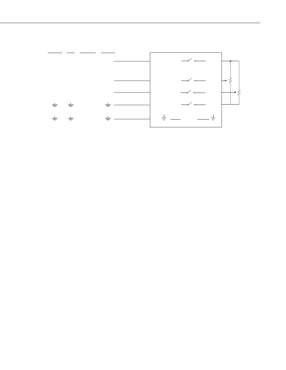
FIGURE 6-4. Potentiometer hookup and measurement (using
CABLE4CBL cable)
CABLE
, up to
tion and ground
uted separately (FIGURE 6-4).
minals are
ne COM
the
e conn
nd. Up to 32 potentiometers
may be measured by two single-ended datalogger channels.
6.3.3 Four Wire Half Bridge (Measured Excitation Current)
Sensor to Multiplexer Wiring — One sensor per input SET. The panel switch
is set to “4x16” mode.
Multiplexer to Datalogger Wiring — One COM line is tied to a datalogger
excitation channel, and two COM lines to a differential analog input. The
remaining COM line is connected to the H side of a datalogger differential
channel along with a fixed resistor. The other side of the resistor connects to
the L side of the differential channel and to ground (FIGURE 6-5). Up to 16
four wire half-bridges may be measured by two differential datalogger
channels in this manner.
6.3.2 Potentiometer Measurement
Sensor to Multiplexer Wiring — If panel switch is set to “4x16” mode
two potentiometers may be connected to one input SET. Excita
leads may be common; signal leads must be ro
Multiplexer to Datalogger Wiring — Signal lines from two COM ter
connected to two consecutive single-ended analog input channels. O
terminal is connected to a datalogger switched excitation channel, and
remaining COM lin
ects to datalogger grou
27