1 heater wiring, 2 wiring for pulse channel input, 3 wiring for control port input – Campbell Scientific 380, 385, 380M, 385M Met One Rain Gages User Manual
Page 13
Met One Rain Gage Models 380 and 385
4.1 Heater Wiring
Attach the power plug supplied with the Model 385 by following the
instructions supplied with the plug. The electric heated snow gage requires
115VAC (50/60hz), 5 amps maximum, to operate the heater. (If supplying
your own signal or power cable, refer to Figure 3-4 for an illustration of cable
installation.) The heater should be unplugged during warmer months to
prevent evaporation during low rainfall and to minimize wear and tear on the
heater element.
The heater thermostat is factory set and requires no field
adjustment.
NOTE
4.2 Wiring for Pulse Channel Input
Connections to Campbell Scientific dataloggers are given in Table 4-1. When
Short Cut for Windows software is used to create the datalogger program, the
sensor should be wired to the channels shown on the wiring diagram created
by Short Cut.
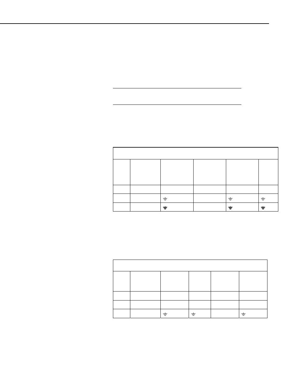
TABLE 4-1. Wiring for Pulse Channel Input
Color
Description
CR800
CR1000
CR3000
CR5000
CR500
CR510,
CR10(X),
21X,
CR7,
CR23X
CR200
Series
Black Signal
Pulse Channel Pulse Channel Pulse Channel P_SW
White Signal
Return
G
Clear Shield
G
Dataloggers listed in Table 4-2 have the capability of counting switch closures
on some of their control ports. When a control port is used, the return from the
rain gage must be connected to +5 volts on the datalogger.
4.3 Wiring for Control Port Input
TABLE 4-2. Wiring for Control Port Input
Color
Description
CR800
CR1000
CR3000
CR500,
CR510
CR10(X)
CR23X
Black Signal
Control Port C2/P3
Control Port Control Port
White Signal Return 5 V
5 V
5 V
5 V
Clear Shield
G
The CR10 does not support the use of control port inputs with the Pulse Count
instruction; use Short Cut or see Example 8.5 in the CR10 operator’s manual.
9