Media Technology Systems AMX 0.2 User Manual
Page 12
Page%12%of%39%
May-10
%
NOTE:!Failure!under!these!conditions!is!not!covered!under!warranty.!!!Always!check!
your!system!grounding.!Never!“lift”!A/C!grounds!on!any!device!in!a!system!in!an!
attempt!to!cure!hum!or!buzz,!so!doing!can!expose!users!to!dangerous!and!lethal!
voltages.!
!
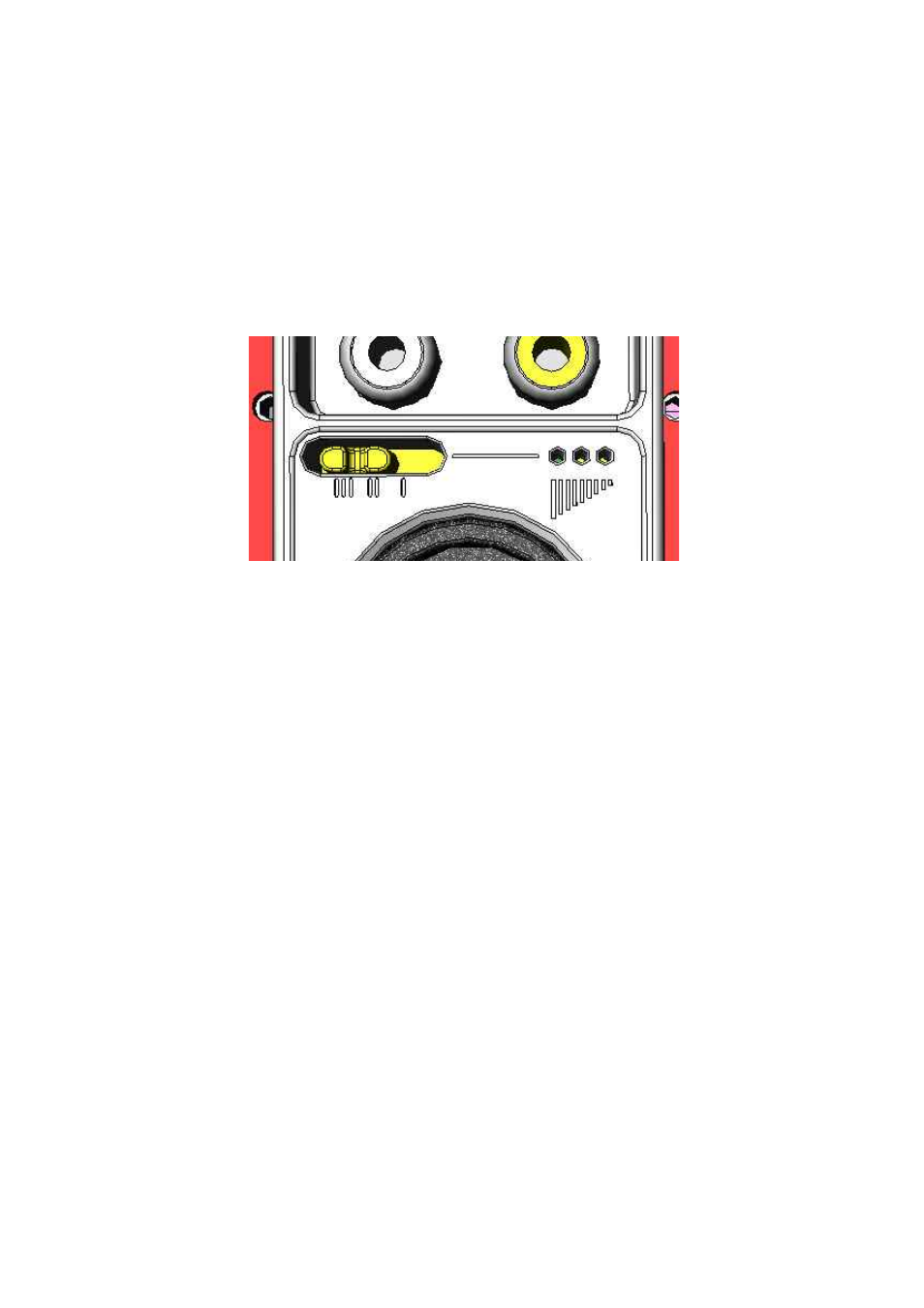
3.3.4 AMX0.2CN&gain&switch&and&indicator&
The!XLR!connector!has!a!gain!switch!with!3!positionsLsee!Figure 3-6.!There!is!also!an!
adjacent!LED!indicator!to!show!the!gain!setting.!!
!
Figure 3-6: Gain switch and LED indicator
The!switch!sets!the!output!sensitivity,!so!that!the!output!of!the!AMX0.2CN!can!match!the!
full!scale/clip!point!of!the!connected!device.!The!switch!should!be!set!to!the!left!for!
more!sensitive!equipment!(ie,!needs!less!signal!level!to!drive!full!output)!and!to!the!
right!for!less!sensitive!equipment!(ie,!needs!more!level!to!drive!full!output).!!The!LED!
and!switch!represents!the!sensitivity!of!the!connected!equipment,!so!that!the!peak!
output!of!the!of!the!AMX0.2CN!increases!from!left!to!right,!where!the!left!position!is!for!
connected!devices!with!a!maximum!capability!of!L8dBu!(nominal,!+12dbu!peak),!the!
middle!position!is!for!connected!devices!with!a!maximum!capability!of!!L2dBu!(nominal,!
+18dbu!peak)!and!the!right!position!is!for!connected!devices!with!a!maximum!
capability!of!!+4dBu!(nominal,!+22dBu!peak).!
3.3.5 Mounting&Position&
The!AMX0.2CN!can!be!mounted!either!way!up,!ie!label!at!the!top!or!label!at!the!bottom.!
However,!it!is!recommended!that!the!AMX0.2CN!be!mounted!label!at!the!bottom,!as!it!
makes!the!gain!position!and!LED’s!easier!to!see,!when!the!XLR!is!connected.!!
!
In!the!situation!where!the!AMX0.2CN!is!mounted!with!the!back!can!installed!for!
protection!(see!Figure 3-7),!then!label!at!the!bottom!position!is!mandatory.!