Legend - fig 2.1 – Samlex America SEC-4825BRM User Manual
Page 5
4 | SAMLEX AMERICA INC.
SAMLEX AMERICA INC. | 5
Section 2 |
Layout, Dimensions &
input/output connections
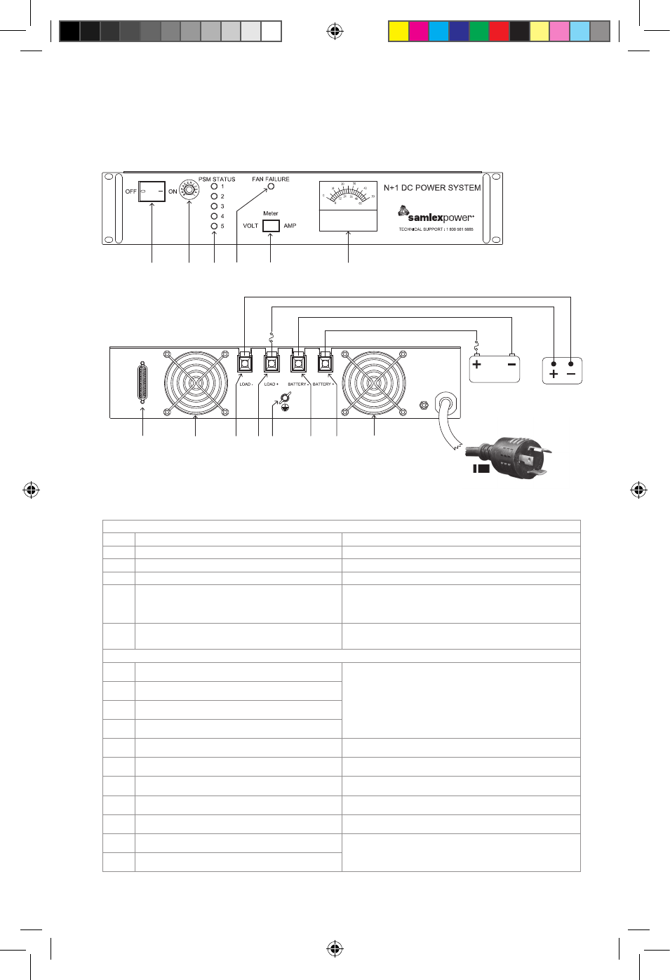
Fig. 2.1 Layout and Input/Output Connections
1
2
5
3
4
6
Fig. 2.1 FRONT VIEW
12
9
9
8A
8B
10
7A
7B
11A
11B
48V Battery
48V Load
F1
Fig. 2.1 BACK VIEW
F2
Legend - Fig 2.1
FRONT VIEW
1
AC Power ON/OFF Switch
Illuminates RED when ON
2
AC Input Breaker
25A.
3
DC Volt Meter / Ammeter
Voltage / current on Load Terminals
4
Voltmeter / Ammeter Selector Switch
Switches display on Voltmeter / Ammeter (3)
5
Green LED for Power Supply Modules (PSM)
1 to 5
STEADY ON: PSM is operating normally
BLINKING: No output. PSM is not synchronizing
OFF: No output. Defective
6
Red LED for fan failure or over temperature
of heat sink on the PSM
STEADY ON: Fan failure or PSM over temperature
BACK VIEW
7A
Positive (+) Load Terminal
TUBULAR HOLE: 5/16” Diameter
SET SCREW: 5/16” X 3/8” Long x 24 TPI
7B
Negative (−) Load Terminal
8A
Positive (+) Battery Terminal
8B
Negative (−) Negative Terminal
9
Cooling Fan
2 x 48V fans. Run continuously
10
Grounding Lug
Connect to Earth Ground / System Ground
11A
Attached AC Input Power Cord
3 Conductors - each AWG #12
11B
AC Input Power Cord Plug
30A, NEMA L5-30P
12
DB-25, D-Sub Connector
For remote signaling (Pin Out - Fig 3.2)
F1
External Battery Side Fuse
25A, 80V (Not supplied)
- ATO Style, FKS Series by Littelfuse
- Part No. 166.7000.525
F2
External Load Side Fuse
11001-SEC-4825BRM-0114.indd 5
14-01-07 1:15 PM