Samlex America SEC-4825BRM User Manual
Page 14
14 | SAMLEX AMERICA INC.
SAMLEX AMERICA INC. | 15
OUTPUT VOLTAGE ADJUSTMENT
As explained earlier, the Power Supply Section of this unit has 5 Power Supply Modules
operating in parallel under forced current share control. Each module has rated current
output of 5A and hence, the total rated current output of the unit is 25A. For the forced
current share / Master –Slave operation to work properly, it is important that the “set
output voltage” of each of the 5 modules is exactly the same. If the output voltage of
any module is below the “set voltage”, its current share control circuitry (slave opera-
tion) will not function properly and it’s associated “PSM x” LED will start fl ashing. The
other modules which are putting out the “set voltage” will function normally under
Master/ Slave operation and their “PSM x” LEDs will remain continuously lighted and
the output voltage of the common DC bus (before Schottky Diode D1) will be equal to
the “set voltage”. If the output voltage of any module is higher than the “set voltage”,
it will become the Master and it’s associated “PSM x” LED will remain continuously
lighted. However, the other Modules with voltage lower than the “set voltage” will
Section 3 |
Design & Principle of operation
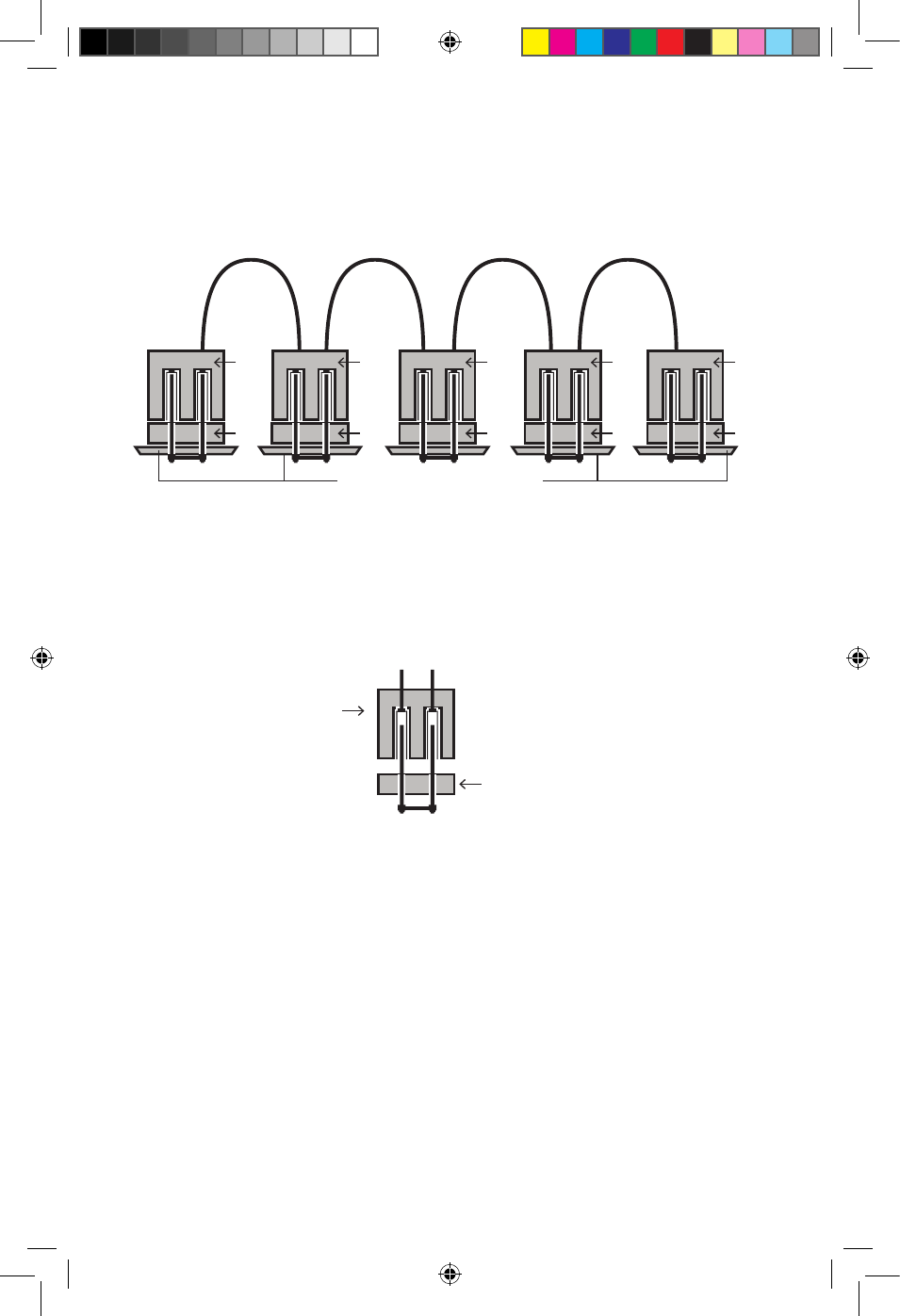
1
2
1
2
1
2
1
2
1
2
PSM 1
PSM 2
PSM 3
PSM 4
PSM 5
PCB (Printed Circuit Board)
Jump 1
Jump 1
Jump 1
Jump 1
Jump 1
Shorting Link
Unused
female
socket
Fig 3.5 Daisy Chaining of Share Bus Jumps (Jump 1)
1
2
1
2
1
2
1
2
1
2
PSM 1
PSM 2
PSM 3
PSM 4
PSM 5
PCB (Printed Circuit Board)
Jump 1
Jump 1
Jump 1
Jump 1
Jump 1
Shorting Link
Unused
female
socket
Fig 3.6 Shorting Unused Jump 1 Daisy Chain Wire Connector
LeGenD:
1. Female terminal for the Daisy Chain Wire Connector
2. Male, 2-pin terminal marked “Jump 1” on the Power Supply Module
11001-SEC-4825BRM-0114.indd 14
14-01-07 1:15 PM