Samlex America SEC-4825BRM User Manual
Page 11
10 | SAMLEX AMERICA INC.
SAMLEX AMERICA INC. | 11
Section 3 |
Design & Principle of operation
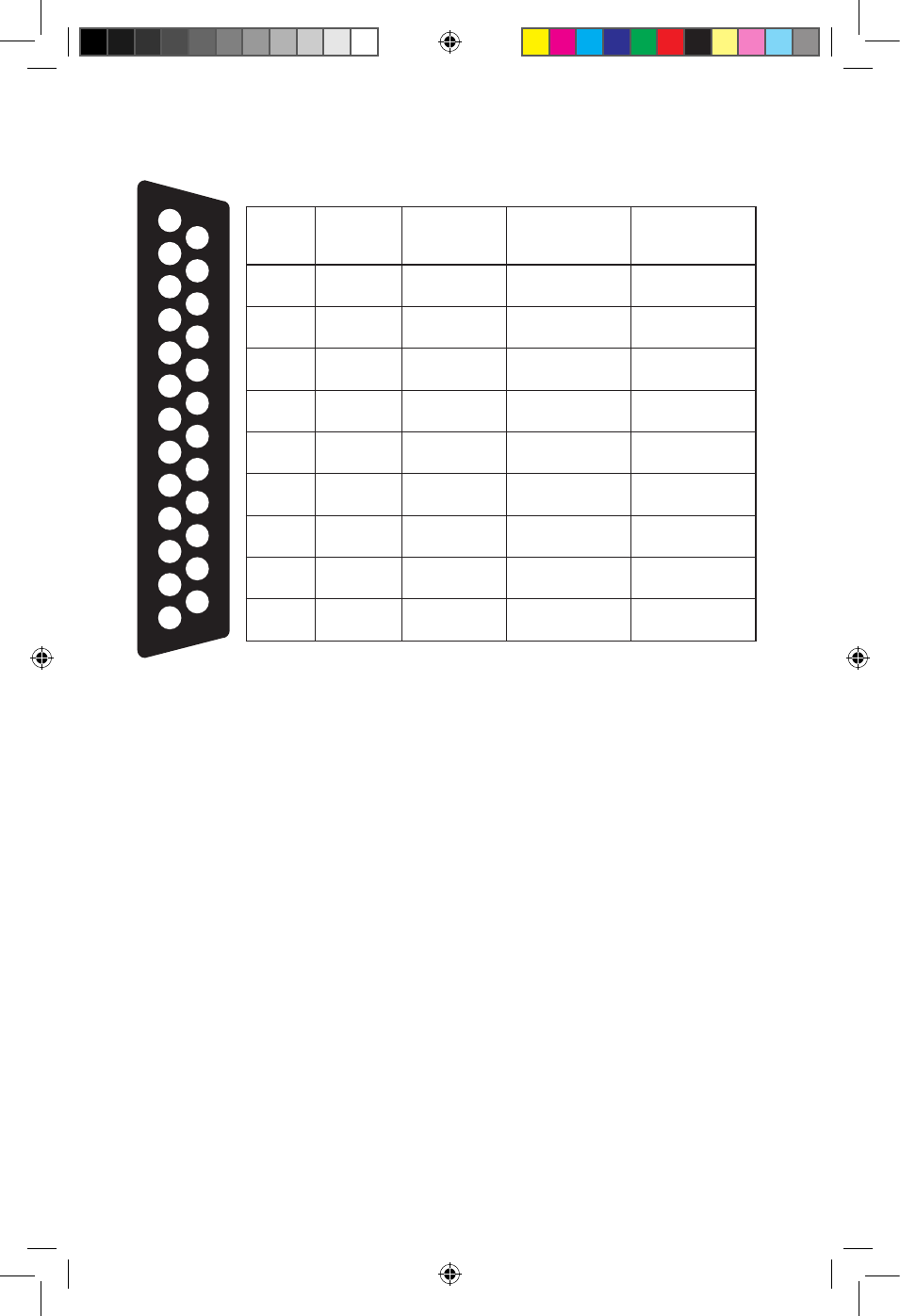
Fig. 3.2 Pin Out of 25 Pin D-Sub Connector (12, Fig 2.1) for Remote Monitoring
OPTO-ISOLATED TRANSFER OF SIGNALS FOR REMOTE MONITORING
In this power supply, signals for remote indication of operating conditions at Serials (a),
(b) and (c) on page 10 are transmitted to the remote receiving device through open
Collector and open Emitter pins of NPN phototransistor of internal Opto-Isolator (Fig 3.2
above and Fig 3.3A on page 12). The NPN phototransistor can provide a maximum of
50 mA with a Collector to Emitter voltage of up to 35V. Use of opto-isolated signal
transfer ensures the following at the receiving location:
• Isolates noise, ground loops, and / or high voltages from the power supply
from being fed to the external remote monitoring device.
• The +Vcc voltage that is connected to the pull-up resistor(s) / alarms and relays for
generating alarm signals at the receiving monitoring device (Figs 3.3 B to D, page 12)
comes from an external voltage source and hence, maximum isolation is provided
• Ability to generate TTL logic signals with Vcc of 3.3V / 5V (Fig 3.3B for 5V Vcc)
• Drive relays / LEDs with Vcc of up to 35VDC (e.g. 5V / 12V / 24V) and drive current of
up to 50 mA (Figs 3.3C and 3.3D)
• Ability to combine the signals (OR’d) to form a single signal sharing common
Logic Ground
Item
Pin No.
Color Code
of Wire
Output Pins of
Opto Isolator
†Operational
Condition or
Parameter (High)
1
2
16
Black
White
Collector
Emitter
AC input is
available
2
12
19
Orange
Green
Collector
Emitter
Fan failure
3
7
20
Gray
Violet
Collector
Emitter
PSM 1 Normal
4
8
21
Violet
Blue
Collector
Emitter
PSM 2 Normal
5
9
22
Blue
Greeb
Collector
Emitter
PSM 3 Normal
6
10
23
Green
Yellow
Collector
Emitter
PSM 5 Normal
7
11
24
Yellow
Orange
Collector
Emitter
PSM 5 Normal
8
25
13
Red
Black
-
Voltmeter +
Voltmeter -
9
18
6
Gray
Blue
-
*Ammeter +
*Ammeter -
1
2
3
4
5
6
7
8
9
10
11
12
13
14
15
16
17
18
19
20
21
22
23
24
25
Notes:
† For operational conditions at Items 1 to 7, the Transistor Switch inside the
Opto Isolator is in “Saturation” condition (near short circuit between
Collector and Emitter terminals)
* Shunt Ratio 25mV/50A or 0.5mV/Amp.
11001-SEC-4825BRM-0114.indd 11
14-01-07 1:15 PM