Not to scale + legend – Samlex America SEC-4825BRM User Manual
Page 13
12 | SAMLEX AMERICA INC.
SAMLEX AMERICA INC. | 13
Principle of operation is explained in Figs 3.3A to 3.3D below using example of remote
monitoring of the operational status of Power Supply Module No. 1 (PSM1).
Operation Inside the Power Supply
Please refer to Fig 3.3A.
When PSM1 is operating normally, 5V (HIGH) drive signal is fed to Pins 1 and 2 of Infra-
red Diode inside the Opto-Isolator “IC1”. The diode conducts and optically transfers
HIGH Base drive condition to the NPN Photo-Transistor with Pin 4 (Open Collector) and
Pin 3 (Open Emitter). The Photo-Transistor will be in “Saturated” condition (near short
circuit between Collector (Pin 4) and Emitter (Pin 3). Pins 4 and 3 are connected to Pins 7
and 20 respectively of the DB25 Connector (Fig 3.2).
Operation at Remote Monitoring Location
Monitoring of status from the DB-25 Connector can be undertaken at the remote
monitoring location in 3 ways shown in Fig 3.3B, 3.3C and 3.3D.
Section 3 |
Design & Principle of operation
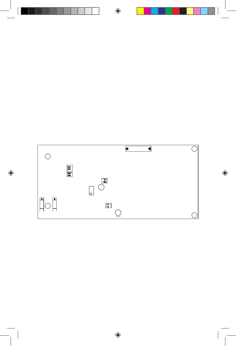
L
N
S2
S1
LED 1
LED 2
S3
S4
S6
S-5
JUMP 1
VCC
VR1
NOT TO SCALE
+
Legend
S1 to S4
Holes for 4 screws to fasten the module to the chassis
S5 & S6
Holes for 2 screws to connect to the Positive & Negative output BUS Bars
L & N
L (Line) and N (Neutral) terminals for 120V, 60 Hz input power supply wires
LED 1
Terminal for remote indication of PSM status
LED 2
Terminal for “LED” PSM status (Front Panel)
JUMP 1
Jumper terminal for connecting share BUS wire
VCC
Connector for feeding Vcc to PCB for fan monitoring
F1
Fuse: 250V, 4A
VR1
Potentiometer for output voltage adjustment
+
F1
Figure 3.4 Layout of Power Supply Module “M20-48V”
11001-SEC-4825BRM-0114.indd 13
14-01-07 1:15 PM