Samlex America SEC-4825BRM User Manual
Page 12
12 | SAMLEX AMERICA INC.
SAMLEX AMERICA INC. | 13
Section 3 |
Design & Principle of operation
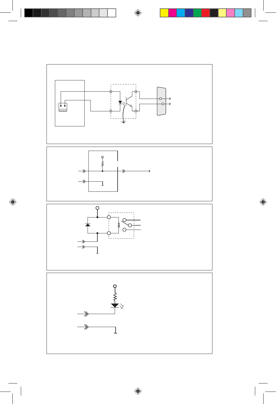
PSM1 PCB
“M-20-48V”
5V
LED 1
PSM GND
GRAY
VIOLET
PIN 1 is
HIGH (5V)
when PSM 1
is Normal
1
4
3
20
Opto-Isolator
PCB “M-20-P”
C
E
DB-25 Connector
GRAY
VIOLET
VCE – Max 35V
IC – Max 50mA
2
7
20
7
To Figures:
3.3B/3.3C/3.3D
Fig. 3.3A: Schematic for Remote Signalling for “PSM 1 Normal”
Fig. 3.3B: 5V TTL Logic Drive
+ Vcc = 5V
Vcc Ground
To Micro-controller
PSM 1 Normal – Low (0 to 0.5V)
PSM 1 Defective – High (2.7V to 5V)
Fig. 3.3C: 5V / 12V / 24V Relay Drive
+ Vcc = 5V / 12V / 24V (Max. 35V)
IN4001
From Fig. 3.3A 20
7
Relay 5V / 12V / 24V:
Choose coil resistance
to limit coil current
to < 50 mA
NC
Common
NO
PSM 1 Normal – Relay energizes
PSM 1 Defective – Relay de-energized
Vcc Ground
PSM 1 Normal – LED “ON”
PSM 1 Defective – LED “OFF”
+ Vcc = 5V/12V/24V (Max. 35V)
1.5K
LED
Vcc Ground
From Fig. 3.3A
20
7
Fig. 3.3D: LED Drive
From Fig. 3.3A
20
7
R
Pull Up
= 10K
IC-1
11001-SEC-4825BRM-0114.indd 12
14-01-07 1:15 PM