2 power/data connector – Matrix Orbital PK162-12 User Manual
Page 13
2.1.1 Power Through DB-9 Jumper
In order to provide power through pin 9 of the DB-9 Connector you must place a solder jumper on the
Power through DB-9 Jumper pictured in
figure 10
below. The PK162-12 allows all voltage models to use the
power through DB-9 option, see table 1 on the following page for display module voltage requirements.
Figure 10: Power Through DB-9 Jumper
WARNING Do not apply voltage through pin 9 of the DB-9 connector
AND through the Power/Data Connector at the same time.
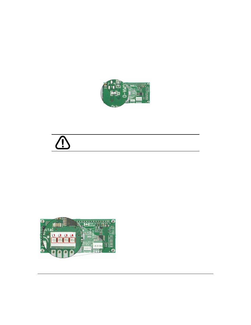
2.2 Power/Data Connector
The Power/Data Connector provides a standard connector for powering the display module. The PK162-
12 requires five volts for the standard display module, between nine to fifteen for the wide voltage (V)
and between nine to thirty-five volts for the wide voltage with efficient power supply module (VPT). The
voltage is applied through pins one and four of the four pin Power/Data connector. Pins two and three are
reserved for serial transmission, using either the RS-232/TTL or the I
2
C protocol, depending on what has
been selected by the Protocol Select Jumpers.
Pin
1
PWR
(See table 1 on the next
page)
Pin
2
Rx \ SCL (I
2
C clock)
Pin
3
Tx \ SDA (I
2
C data)
Pin
4
GND
Figure 11: Power Connector and Pin out
Matrix Orbital
PK162-12
9