Matrix Orbital GLK12232-25-WBL User Manual
Page 9
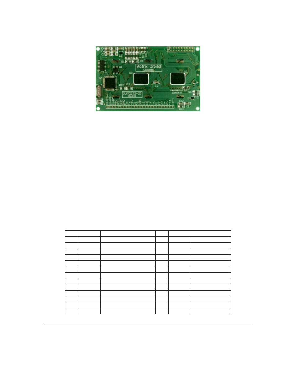
Figure 2: Electrical Connections
All connections are made via a 25 pin in-line connector area near the bottom edge of the PCB. Pin
descriptions are as follows;
Table 1: Pin Descriptions
Pin
Marked
Function
Pin
Marked
Function
1
Yellow
do not use
14
C1
Keypad column 1
2
Black
ground
15
C2
Keypad column 2
3
Black
ground
16
C3
Keypad column 3
4
Red
+5V power input
17
C4
Keypad column 4
5
SCL
I
2
C clock
18
C5
Keypad column 5
6
SDA
I
2
C data
19
R1
Keypad row 1
7
GND
ground
20
R2
Keypad row 2
8
Rx
RS-232 receive data
21
R3
Keypad row 3
9
Tx
RS-232 transmit data
22
R4
Keypad row 4
10
+5V
+5V power input
23
R5
Keypad row 5
11
G1
General purpose output 1
24
Rst
do not use
12
G2
General purpose output 2
25
Cont
do not use
13
GND
ground for GPOs
Matrix Orbital
GLK12232-25-WBL
5
See also other documents in the category Matrix Orbital Hardware:
- GTT35 (19 pages)
- GTT50A (53 pages)
- GTT70A (19 pages)
- GTT38A (19 pages)
- GTT43A (19 pages)
- GTT50A (19 pages)
- GTT Example Files (2 pages)
- GX24064 (24 pages)
- GLT24064R-1U (72 pages)
- GLT24064 (71 pages)
- GLT24064 Legacy (56 pages)
- GLK24064-25 Legacy (41 pages)
- GLK24064-25 Legacy (47 pages)
- GLK24064-25 Legacy (68 pages)
- GLT240128 (70 pages)
- GLT240128 Legacy (70 pages)
- GLK12232-25-SM (70 pages)
- GLK12232-25-SM Legacy (41 pages)
- GLK12232-25-SM Legacy (42 pages)
- GLK12232-25-FGW (66 pages)
- GLK19264A-7T-1U (68 pages)
- GLK240128-25 Legacy (67 pages)
- GLC24064 (44 pages)
- GLC24064 (63 pages)
- GLK19264-7T-1U (71 pages)
- GLK24064-16-1U (48 pages)
- VK162-12 (41 pages)
- LK162-12 Legacy (37 pages)
- LK162-12 Legacy (42 pages)
- LK162A-4T (36 pages)
- LK162B-7T (37 pages)
- VK202-25-USB (42 pages)
- LK202-25 Legacy (20 pages)
- LK202-25 Legacy (37 pages)
- LK202-25 Legacy (50 pages)
- VK204-25 (47 pages)
- LK204-25 Legacy (33 pages)
- LK204-25 Legacy (62 pages)
- LK204-7T-1U (40 pages)
- LK402-25 (43 pages)
- LK402-25 Legacy (56 pages)
- LK404-25 (37 pages)
- LK202-24-USB (36 pages)
- LK202-24-USB (48 pages)