Matrix Orbital GLK12232-25-WBL User Manual
Page 10
2.1.1
Power Connections
WARNINGS
• Do not apply any power with reversed polarization.
• Do not apply any voltage other than the specified voltage.
• Do not use any cables other than the cables supplied by Matrix
Orbital, unless aware of the modifications required.
• Do not under any circumstances use an unmodified floppy drive
power cable.
• Do not apply power to both the DB-9 connector AND the 4-pin
power connector.
• Do not apply more than +5Vdc to pin #9 of the DB-9 connector.
2.1.2
RS-232 Communications
A group of four connections (pins 7-10) provide for RS-232 communications and power. A 4 pin SIP
connector soldered to these pins can be connected to a Matrix Orbital supplied PC cable.
The RS-232 connector on the PC cable is wired so that a standard ’straight through’ 9 pin D-sub cable
may be used to connect the modules to a standard serial port such as COM ports on PCs. Note that this
device complies with the EIA232 standard in that it uses signal levels from +/- 3V to +/- 12V. It will not
operate correctly at TTL (0 to +5V) levels.
Table 2: RS-232 Pinout
Pin Number
Direction
Description
LCD
Host
2
Data from LCD
Data Out (LCD)
Tx
Rx
3
Data to LCD
Data In (LCD)
Rx
Tx
5
-
Ground
gnd
gnd
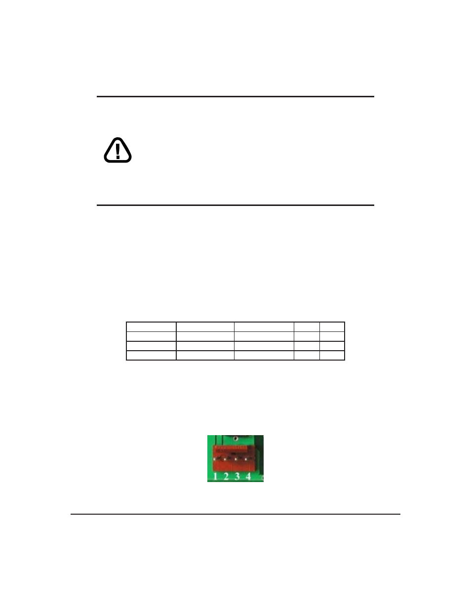
2.1.3
I
2
C Communications
The display has I
2
C communications runs at 100 Kbps and supports up to 127 units on a single com-
munications line. The I
2
C data line operates on 5 volt CMOS levels. The power connector is also the I
2
C
communication line.
Figure 3: Power and I
2
C Connector
Matrix Orbital
GLK12232-25-WBL
6