1 general, 2 graphics commands – Matrix Orbital GLK12232-25-WBL User Manual
Page 15
4.1
General
Since the display is a bit mapped device, it may be used to display graphics. Graphic images may be
created by means of a pixel-oriented graphics program, saved as bitmaps, and loaded into the display using
the mogd.exe program. Images may be saved in the display’s memory, and displayed upon command, or
they may be downloaded ’on the fly’ (inline) during display operation.
Note that ’saved’ and ’on the fly’ graphics images are processed differently. These differences must be
taken into account when processing graphics.
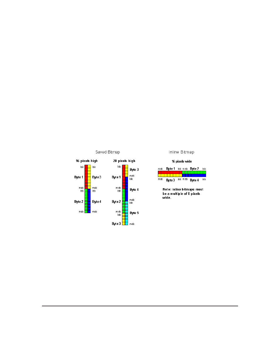
• Saved bitmaps: These use each byte (8 bits) to represent a vertical column of 8 pixels. The next byte
represents the next column to the right. If the graphic is ’taller’ than 8 pixels, the LSB of the next data
byte will be the next pixel. Orientation is top to bottom - LSB to MSB. Pixels / bits are ’packed’ - that
is, if the height of the graphic is not an even multiple of 8, the leftover bits go on the next X column
to the right, etc.
• Inline bitmaps: These are processed horizontally, and each byte represents a horizontal row of 8 bits,
with the next byte representing the next 8 bits to the right. Orientation is left to right - MSB to LSB,
which is the opposite to the serial transmission sequence (bytes are sent LSB first).
Figure 6: Graphic Bitmaps
Each pixel in a bitmap is described by a single bit, and may only have the values ON or OFF. For
example, shades of grey are not supported.
4.2
Graphics Commands
In this section commands are identified by their names and decimal values. Hex and ASCII equivalents
are given in the summary.
The coordinate origin (0,0) is at the top left corner of the display. X values go from 0 to 239 (increasing
toward the right) and Y values go from 0 to 63 (increasing toward the bottom).
Matrix Orbital
GLK12232-25-WBL
11