3 protocol select jumpers – Matrix Orbital GLC24064 User Manual
Page 12
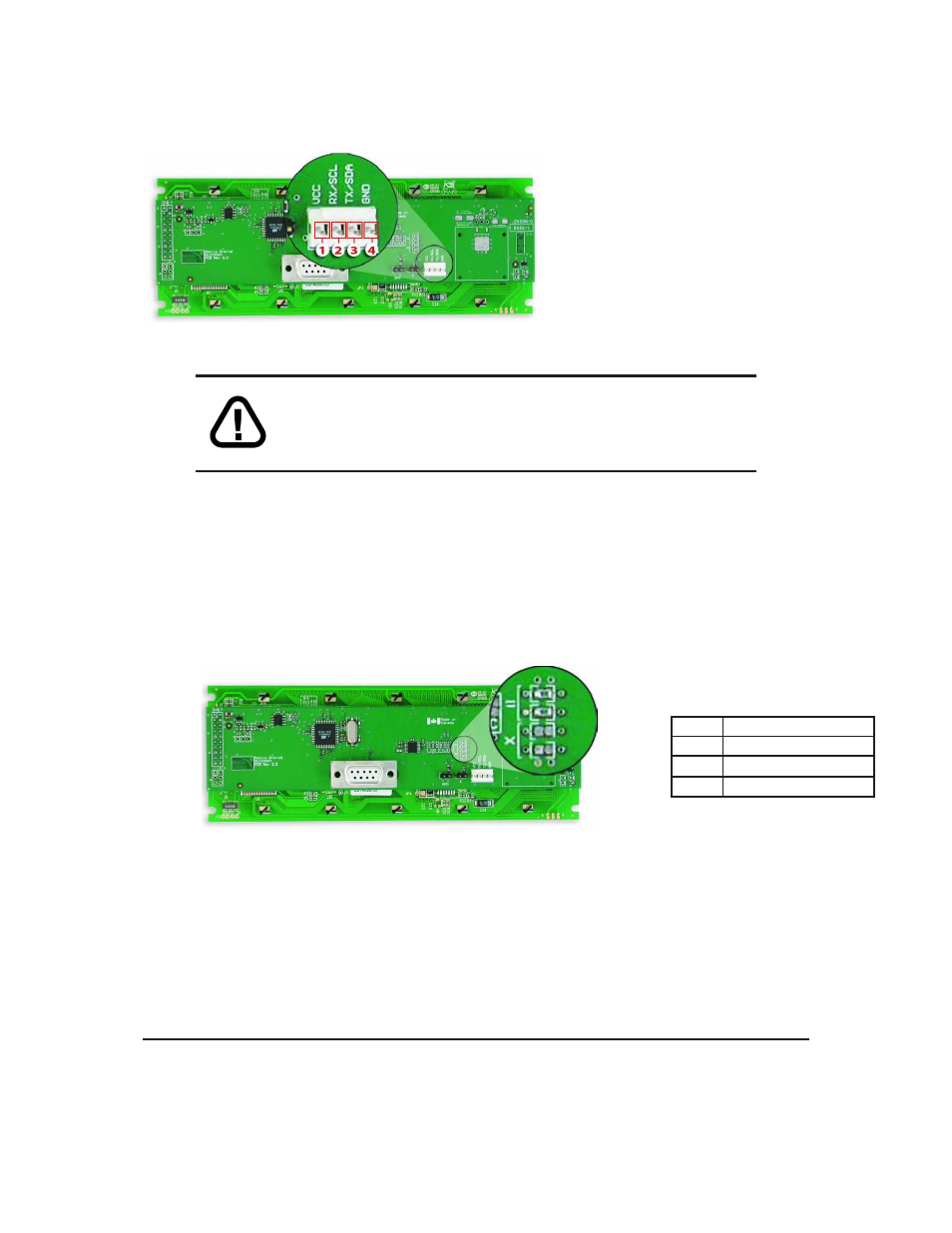
Pin
1
PWR
(See table ?? on page ??)
Pin
2
Rx \ SCL (I
2
C clock)
Pin
3
Tx \ SDA (I
2
C data)
Pin
4
GND
Figure 13: Power Connector and Pin out
WARNINGS
• Do not apply any power with reversed polarization.
• Do not apply any voltage other than the specified voltage.
2.2.1
Legacy Data Connector Jumpers
To reverse pins two and three of the Power/Data Connector remove the zero ohm resistors from the
Legacy Data Connector Jumpers, labeled with the
=
symbol and place them on the jumpers labeled with the
X
symbol. This will allow you to transmit on pin two, and receive data on pin three instead of the default
of receiving on pin two and transmitting on pin three of the Power/Data Connector.
Power/Data Connector
=
[
Pin 2
Rx \ SCL (I
2
C clock)
Pin 3
Tx \ SDA (I
2
C data)
x
[
Pin 2
Tx \ SDA (I
2
C data)
Pin 3
Rx \ SCL (I
2
C clock)
Figure 14: Legacy Data Connector Jumpers
2.3
Protocol Select Jumpers
The Protocol Select Jumpers, pictured below in
figure 15
, provide the means necessary to toggle the
display module between RS-232, TTL and I
2
C protocols. As a default, the jumpers are set to RS-232 mode
with zero ohm resistors on the 232 jumpers. In order to place the display module in I
2
C mode you must
first remove the zero ohm resistors from the 232 jumpers and then solder the resistors on to the I2C jumpers.
Matrix Orbital
GLC24064
7