2 power/data connector – Matrix Orbital GLC24064 User Manual
Page 11
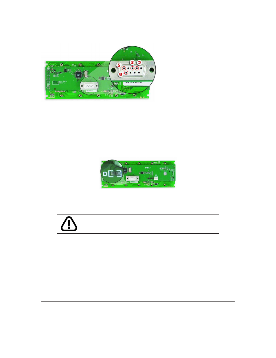
Pin
2
Rx \ SCL (I
2
C clock)
Pin
3
Tx \ SDA (I
2
C data)
Pin
5
GND
Pin
9
PWR
(Must solder Power Through DB-
9 Jumper. See table ?? on page ?? for
power requirements.)
Figure 11: RS-232 Pin out
2.1.1
Power Through DB-9 Jumper
In order to provide power through pin 9 of the DB-9 Connector you must place a solder jumper on the
Power through DB-9 Jumper pictured in
figure 12
below. The GLC24064 allows all voltage models to use
the power through DB-9 option, see table ?? on page ?? for display module voltage requirements.
Figure 12: Power Through DB-9 Jumper
WARNING
Do not apply voltage through pin 9 of the DB-9 connector
AND through the Power/Data Connector at the same time.
2.2
Power/Data Connector
The Power/Data Connector provides a standard connector for powering the display module. The GLC24064
requires five volts for the standard display module, between nine to fifteen for the wide voltage (V) and be-
tween nine to thirty-five volts for the wide voltage with efficient power supply module (VPT). The voltage is
applied through pins one and four of the four pin Power/Data connector. Pins two and three are reserved for
serial transmission, using either the RS-232/TTL or the I
2
C protocol, depending on what has been selected
by the Protocol Select Jumpers. Pins two and three may be reversed by changing the Legacy Connector
Jumpers in order to be compatible with previous PCB revisions.
Matrix Orbital
GLC24064
6