3 gpo, 4 protocol select jumpers – Matrix Orbital GLK12232-25-FGW User Manual
Page 14
2.3
GPO
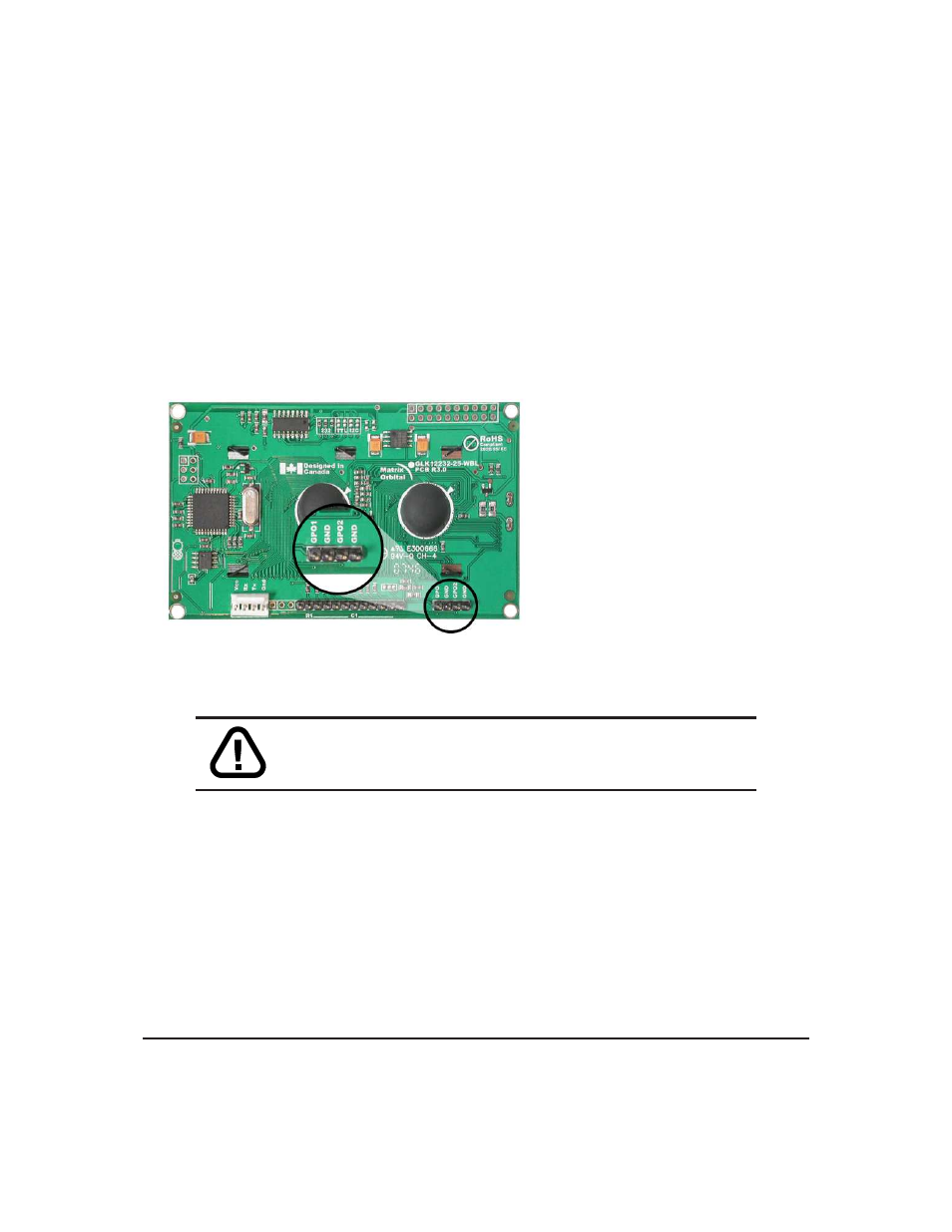
A unique feature of the GLK12232-25 is the ability to control relays and other external devices using a
General Purpose Output (3), which can provide up to 20 mA of current and +5Vdc from the positive side of
the GPO. This is limited by a 240 ohm resistor which is located directly above the positive pin as pictured
below in
figure 14
. If the device, which is being driven by a GPO, requires a relatively high current (such as
a relay) and has an internal resistance of its own greater than 250 ohms, then the 240 ohm resistor may be
removed and replaced with a Jumper.
Pin
1
- GND
Pin
2
+ MAX: 20 mA, +5Vdc
Figure 14: General Purpose Output
WARNING
If connecting a relay, be sure that it is fully clamped using
a diode and capacitor in order to absorb any electro-motive force (EMF)
which will be generated.
2.4
Protocol Select Jumpers
The Protocol Select Jumpers, pictured below in
figure 15
, provide the means necessary to toggle the
display module between RS-232, TTL and I
2
C protocols. As a default, the jumpers are set to RS-232 mode
with zero ohm resistors on the 232 jumpers. In order to place the display module in I
2
C mode you must
first remove the zero ohm resistors from the 232 jumpers and then solder the resistors on to the I
2
C jumpers.
The display will now be in I
2
C mode and have a default slave address of 0x50 unless it has been changed.
Similarly, in order to change the display to TTL mode, simply remove the zero ohm resistors from the 232
or I
2
C jumpers and solder them to the TTL jumpers.
Matrix Orbital
GLK12232-25
9