Ashcroft 4480 - Pneumatic Transmitter User Manual
Page 5
5
Air Connections
Connect the LOW pressure instrument air SUPPLY to the
1
⁄
4
female NPT connection, marked SUPPLY, at the left of the
process pressure connection. The instrument air is to he
clean, dry, and liquid free. Connect the remote equipment
line to the
1
⁄
4
female NPT connection, marked OUTPUT, at
the right. The use of metal or plastic tubing in place of piping
is strongly recommended. It is important that the transmitted
airline be free of leaks: the use of metal or plastic tubing
reduces the possibility of leaks. The supply air pressure
required for 3-15 psi transmitted range is 18-20 psi.
The supply air pressure required for 3-27 psi transmitted
range is 30-35 psi.
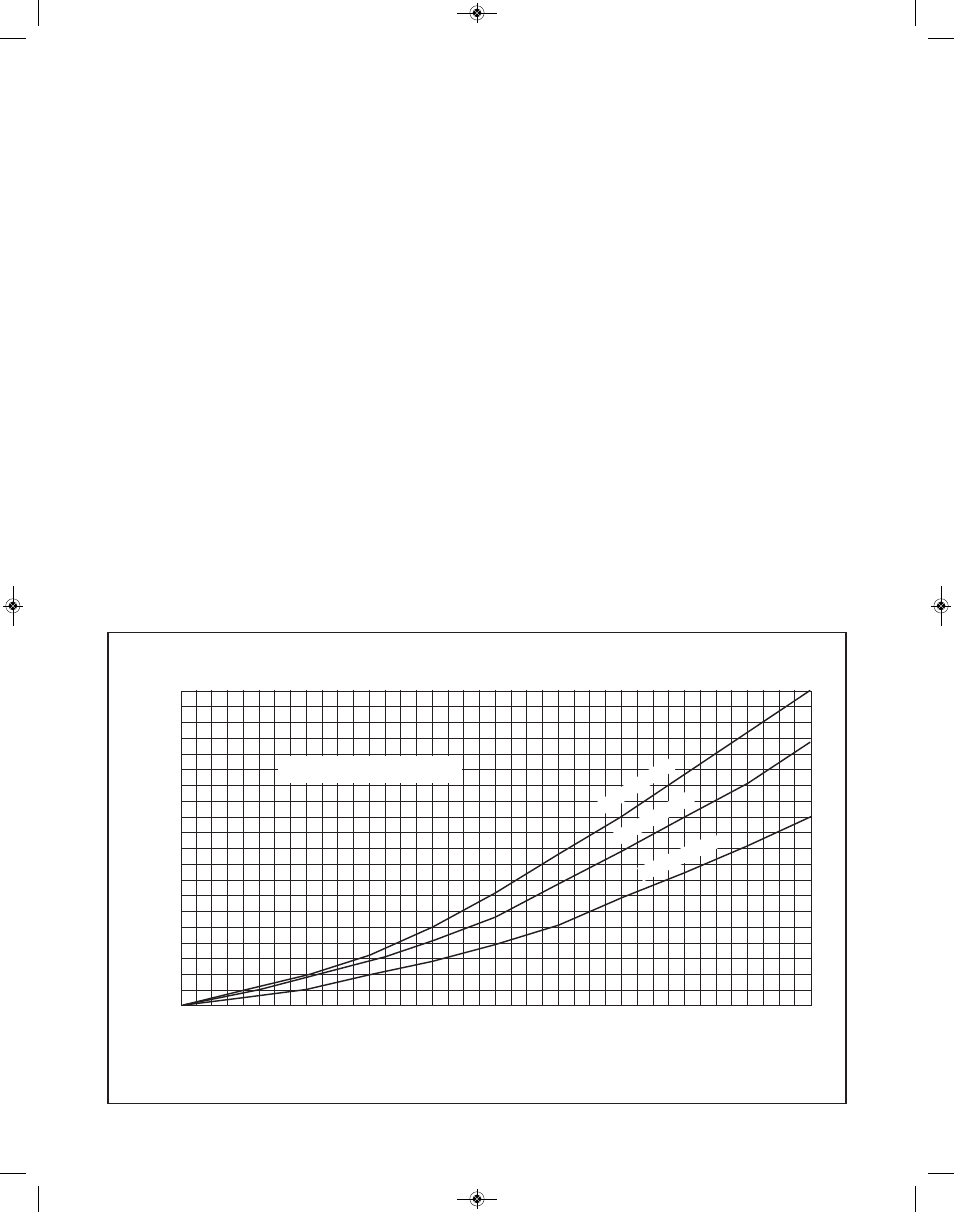
Any number of pneumatic receivers may be connected to the
transmitted air line. However, the total length of the transmit-
ted air line should not exceed 1000 feet, or the speed of
response will be reduced. Response speed versus line length
for various sizes of tubing Is shown In Figure 6.
Figure 6. Response Speed versus Tubing Diameter and Length
50
45
40
35
30
25
20
15
10
5
0
100
200
300
400
500
600
700
800
900
1000
FEET OF TUBING
T
IM
E
I
N
S
E
C
O
N
D
S
RESPONSE TIME
TIME REQUIRED TO CHANGE
RECEIVER INDICATION 100%
3
⁄
16
˝ I
.D
. T
UB
IN
G
1
⁄
4
˝ I.
D.
TU
BIN
G
5
⁄
16
˝ I.
D. T
UB
ING
I&M008-10061-1-01 250-1969-C_I&M008-10061-1/01 250-1969-C 12/20/13 9:09 AM Page 5