Installation – Ashcroft 4480 - Pneumatic Transmitter User Manual
Page 4
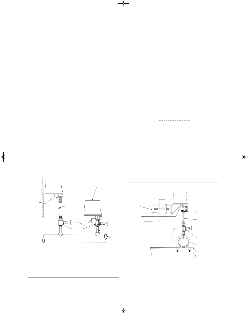
ON STEAM LINES A
SYPHON MUST BE USED.
ON HIGH TEMPERATURE
LINES TWO FEET OF
PIPE SHOULD BE USED
TO INSURE COOLING OF
THE LIQUID. TUBING IS
RECOMMENDED IN
PLACE OF PIPE ABOVE
THE VALVE.
UNION
SHUT-OFF VALVE
ADJUSTABLE
BRACKET
1
⁄
4
NPTF AIR
SUPPLY AND
OUTPUT
CONNECTIONS
2˝ PIPE
SUPPORT POST
CENTER OF SUP-
PORT TO CENTER
OF PIPE LINE
ADJUSTABLE
BETWEEN 5
1
⁄
16
˝
AND 12
13
⁄
16
˝
PIPE SUPPORT
GOOD INSTALLATION PRACTICE DICTATES THAT THE INSTALLATION SHOULD BE FREE OF VIBRATION AND PIP-
ING STRAIN. IF THERE IS VIBRATION IN THE PIPE LINE. THE 2˝ PIPE SUPPORT SHOULD BE MOUNTED ON
SOME INDEPENDENT MEMBER AND THE PRESSURE CONNECTION TO THE TRANSMITTER SHOULD BE TUB-
ING WITH SUFFICIENT FLEXIBILITY TO DAMPEN THE VIBRATION.
PIPE LINE
Figure 5. Pipe-Mounted Pressure Transmitter Installation
4
PIPE LINE
Mounting
Ashcroft pressure transmitters are designed for bracket
mounting (refer to Fig. 4), to ensure free action of all compo-
nents, thereby maintaining accurate calibration. The transmit-
ters may be pipe mounted, wall mounted or stem mounted.
Typical methods of mounting are shown in Figures 4 and 5.
Applicable dimensions are given in the illustrations.
For most trouble-free performance, transmitters should be
mounted vertically. Some loss of accuracy may result from
angular mounting; this may be minimized by recalibration after
mounting.
The transmitters have been designed to withstand severe pul-
sation and vibration. However, in keeping with good instrument
practice, it is recommended that they be installed so as to min-
imize vibration and pulsation.
Ambient Conditions
Ashcroft transmitters are temperature compensated for the
normal range of ambient temperatures. Extremes of ambient
temperature may result in inaccuracies. The transmitter should
not be subjected to temperatures exceeding 150˚F. If the
process temperature will exceed this limit, install a diaphragm
seal or suitable length of pipe to protect the transmitter from
excessive temperatures. If very low temperatures will be
encountered, make certain to eliminate any possibility of mois-
ture in the air lines. Condensation and vaporization of moisture
in air lines cause unpredictable variations in accuracy. For low
ambient temperature installation, a case heating device is rec-
ommended.
STEM MOUNTING NOT
SUITABLE FOR STEAM
OR WHERE THE PIPE
LINE IS VIBRATING OR
VERY HOT
TUBING WITH
BENDS FOR
FLEXIBILITY.
FOR STEAM, A
SYPHON MUST
BE USED WITH
THE TUBING.
WALL OR
COLUMN
BRACKET
MAY BE
REMOVED
SHUT-OFF
VALVES
1
⁄
2
˝
CONNECTION
1
⁄
2
˝ OR
LARGER PIPE
Figure 4. WaIl and Stem-Mounted Pressure Transmitter Installation
NOTES:
PULSATIONS SHOULD BE DAMPENED BY SUITABLE THROTTLING DEVICES.
AS USED ON PRESSURE GAUGES AND LISTED IN THE ASHCROFT GAUGE
ACCESSORY CATALOG
DIAPHRAGM SEALS MAY BE INSTALLED DIRECTLY TO THE TRANSMITTER OR
WITH A CAPILLARY LINE. (BOURDON TUBE ELEMENTS ONLY.
SUPPLY AND OUTPUT AIR CONNECTIONS ARE
1
⁄
4
NPT FEMALE.
DRAIN OR VENT VALVES SHOULD BE INSTALLED ABOVE THE SHUT OFF
VALVE ON HIGH PRESSURE GAS OR DANGEROUS LIQUID INSTALLATIONS.
INSTALLATION
Steam Pressure Measurement
When a transmitter is used for steam pressure measurement,
a siphon filled with water must be installed between the line
and the input element. When the system is subject to occa-
sional vacuum, provide a length of piping which cannot be
emptied by the vacuum. Install a drain cock or plug at the bot-
tom of this leg to provide for cleaning out sediment. Refer to
the Calibration section for the method of zeroing the transmit-
ter to compensate for the “head” effect of introducing the con-
densate water leg.
Pressure Connection
The process pressure connection is the center connection at
the bottom of the transmitter. Always use a wrench on the flats
of the process connection to avoid applying strain to socket
mounting screws and the internal mechanism.
CAUTION
Avoid piping strains in accordance with good installation prac-
tice except in the case of stem mounting, it is preferable to use
flexible tubing for the last length of piping leading to the
transmitter.
I&M008-10061-1-01 250-1969-C_I&M008-10061-1/01 250-1969-C 12/20/13 9:09 AM Page 4