Terminal block connections, Figure 3: external relays module connections – Ashcroft DM61 User Manual
Page 7
101B224-03 & 101B224-04 Expansion Modules Instruction Manual
7
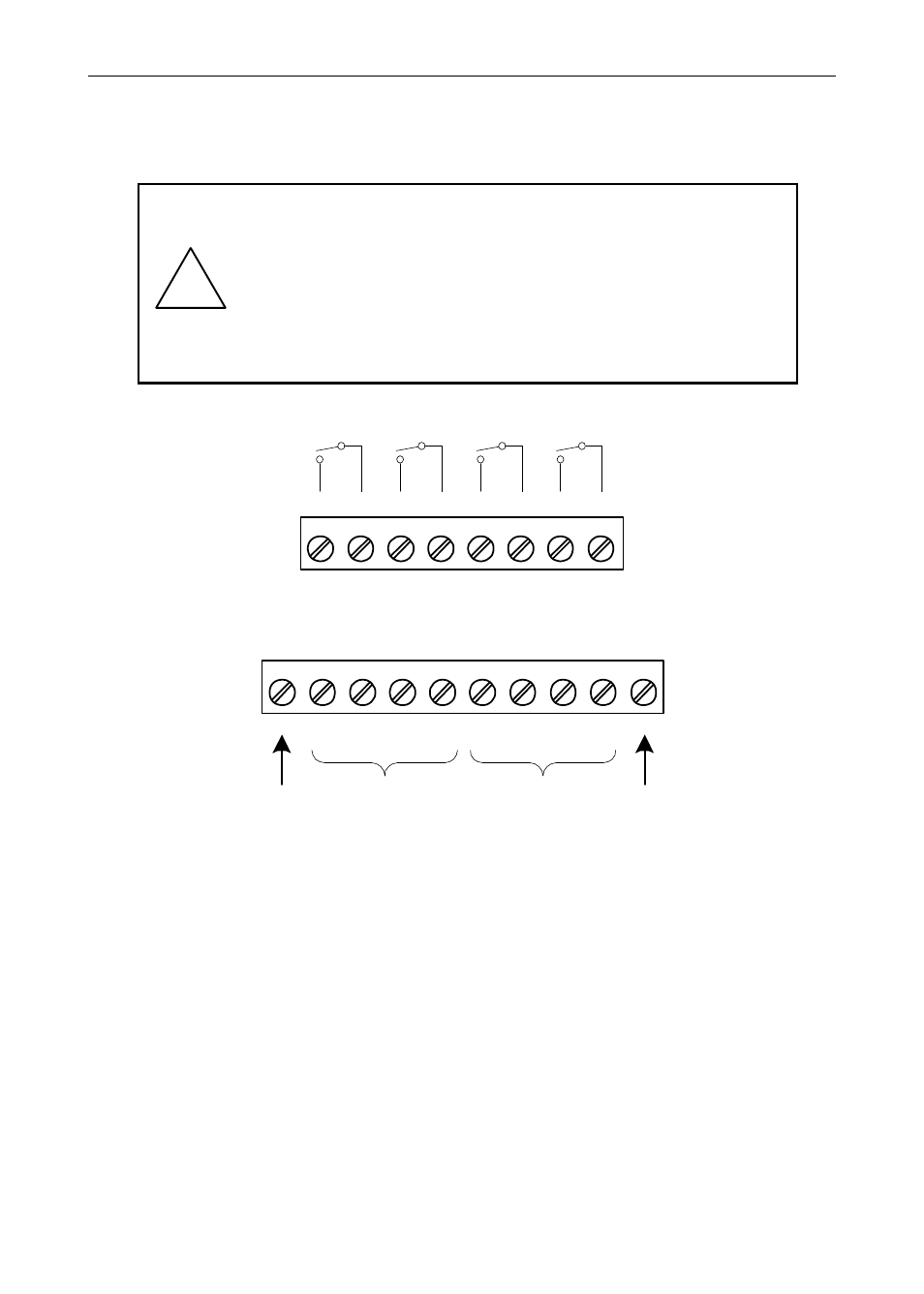
Terminal Block Connections
All connections are made to removable screw terminal connectors
located at the front of the module.
!
Use copper wire with 60°C (140°F) or 60/75°C
(140/167°F) insulation for all line voltage connec-
tions. Observe all safety regulations. Electrical wir-
ing should be performed in accordance with all
applicable national, state, and local codes to pre-
vent damage to the meter and ensure personnel
safety.
1
2
RLY5
RLY6
RLY7
RLY8
3
4
5
6
7
8
NO
C
NO
C
NO
C
NO
C
Figure 3: External Relays Module Connections
1
2
3
4
5
6
+5
I1
I2
I3
I4
O1
7
8
O2
O3
9
10
O4
G
DI 1-4
DO 1-4
5 VDC
GND
Figure 4: Digital I/O Module Connections
See also other documents in the category Ashcroft Measuring instruments:
- 2089 Precision Digital Test Gauges (20 pages)
- A4A - Dial Pressure Gauge (2 pages)
- 1082 - Pressure Test Gauge (20 pages)
- 1279 - Receiver Gauges (2 pages)
- 2279 - Duratran® Pressure Transmitter (2 pages)
- 1038A - Duplex Gauge (20 pages)
- 1125 - Differential Pressure Gauge (1 page)
- 1130 - Differential Pressure Gauge (2 pages)
- 1131 - Differential Pressure Gauge (2 pages)
- 1132 - Differential Pressure Gauge (2 pages)
- 1131 - Differential Pressure Gauge (2 pages)
- 1133 - Differential Pressure Gauge (2 pages)
- 1134 - Differential Pressure Gauge (2 pages)
- 2032 - Digital Sanitary Pressure Gauge (32 pages)
- DG25 General Purpose Digital Gauge (16 pages)
- 2074 Digital Industrial Gauge (32 pages)
- 2084 Precision Digital Test Gauge (20 pages)
- A2 - Heavy industrial pressure transmitter (4 pages)
- A2X - Pressure Transmitter (2 pages)
- A4 - Pressure Transmitter (6 pages)
- G2 - High Performance Pressure Transducer (2 pages)
- GC31 - Digital Pressure Sensor (20 pages)
- GC35 - Pressure Sensor (4 pages)
- GC35 - Pressure Sensor (20 pages)
- GC51 - Industrial Rangeable Pressure Transmitter (2 pages)
- GC51 - Industrial Rangeable Pressure Transmitter (4 pages)
- GC51 - Industrial Rangeable Pressure Transmitter (32 pages)
- GC55 - Differential Pressure Transducer with Digital Display (24 pages)
- H2 - Precision Pressure Transducer (2 pages)
- K1 - Industrial Pressure Transducer (2 pages)
- KM10 - Compact Pressure Transducer (2 pages)
- KM15 - Compact Pressure Transducer (2 pages)
- KS - Sanitary Pressure Transmitter (2 pages)
- KX - Flush Mount Pressure Transmitter (2 pages)
- DM61 (20 pages)
- CXLdp - Differential Pressure Transmitter (2 pages)
- DXLdp - Differential Pressure Transmitter (2 pages)
- GC30 Ultra-Compact Differential Pressure Sensor (20 pages)
- GC52 - Rangeable wet/wet Differential Pressure Transmitter (2 pages)
- GC52 - Rangeable wet/wet Differential Pressure Transmitter (28 pages)
- GC52 - Rangeable wet/wet Differential Pressure Transmitter (16 pages)
- GC52 - Rangeable wet/wet Differential Pressure Transmitter (40 pages)
- GL42 - Low Differential Indicating Pressure Transmitter (4 pages)
- IXLdp - Low Differential Pressure Transmitter (2 pages)