Installation, External relays & digital i/o connections – Ashcroft DM61 User Manual
Page 6
101B224-03 & 101B224-04 Expansion Modules Instruction Manual
6
INSTALLATION
There is no need to remove the expansion module from its
case to complete the installation, wiring, or setup of the unit.
WARNING!
Do not connect or disconnect the expansion module
with the power on!
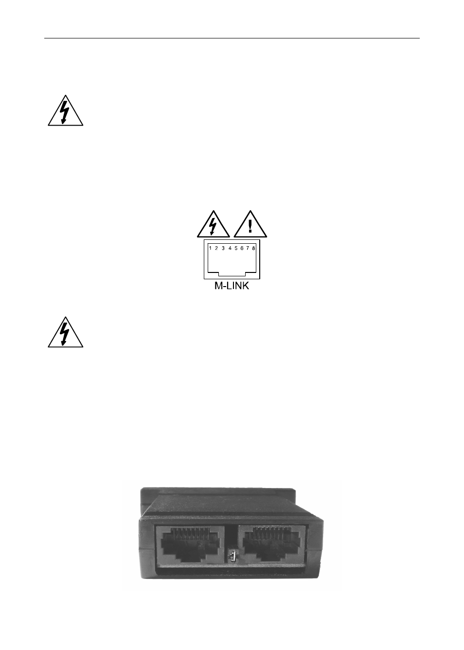
External Relays & Digital I/O Connections
The relay and the digital I/O expansion modules 101B224-03 &
101B224-04 are connected to the meter using a CAT5e cable provided
with each module (see Figure 1).
Figure 1: M-Link Connector Location on the Meter
WARNING!
Do not connect any equipment other than Ashcroft’s
expansion modules, cables, or meters to the RJ45
M-LINK connector. Otherwise damage will
occur to the equipment and the meter.
The two RJ45 connectors on the expansion modules are identical and
interchangeable; they are used to connect additional modules to the
system.
Note: The jumper located between the RJ45 connectors of the
101B224-04 (see Figure 2) must be removed on the second digi-
tal I/O module in order for the system to recognize it as module
#2.
Figure 2: Jumper Location
- 2089 Precision Digital Test Gauges (20 pages)
- A4A - Dial Pressure Gauge (2 pages)
- 1082 - Pressure Test Gauge (20 pages)
- 1279 - Receiver Gauges (2 pages)
- 2279 - Duratran® Pressure Transmitter (2 pages)
- 1038A - Duplex Gauge (20 pages)
- 1125 - Differential Pressure Gauge (1 page)
- 1130 - Differential Pressure Gauge (2 pages)
- 1131 - Differential Pressure Gauge (2 pages)
- 1132 - Differential Pressure Gauge (2 pages)
- 1131 - Differential Pressure Gauge (2 pages)
- 1133 - Differential Pressure Gauge (2 pages)
- 1134 - Differential Pressure Gauge (2 pages)
- 2032 - Digital Sanitary Pressure Gauge (32 pages)
- DG25 General Purpose Digital Gauge (16 pages)
- 2074 Digital Industrial Gauge (32 pages)
- 2084 Precision Digital Test Gauge (20 pages)
- A2 - Heavy industrial pressure transmitter (4 pages)
- A2X - Pressure Transmitter (2 pages)
- A4 - Pressure Transmitter (6 pages)
- G2 - High Performance Pressure Transducer (2 pages)
- GC31 - Digital Pressure Sensor (20 pages)
- GC35 - Pressure Sensor (4 pages)
- GC35 - Pressure Sensor (20 pages)
- GC51 - Industrial Rangeable Pressure Transmitter (2 pages)
- GC51 - Industrial Rangeable Pressure Transmitter (4 pages)
- GC51 - Industrial Rangeable Pressure Transmitter (32 pages)
- GC55 - Differential Pressure Transducer with Digital Display (24 pages)
- H2 - Precision Pressure Transducer (2 pages)
- K1 - Industrial Pressure Transducer (2 pages)
- KM10 - Compact Pressure Transducer (2 pages)
- KM15 - Compact Pressure Transducer (2 pages)
- KS - Sanitary Pressure Transmitter (2 pages)
- KX - Flush Mount Pressure Transmitter (2 pages)
- DM61 (20 pages)
- CXLdp - Differential Pressure Transmitter (2 pages)
- DXLdp - Differential Pressure Transmitter (2 pages)
- GC30 Ultra-Compact Differential Pressure Sensor (20 pages)
- GC52 - Rangeable wet/wet Differential Pressure Transmitter (2 pages)
- GC52 - Rangeable wet/wet Differential Pressure Transmitter (28 pages)
- GC52 - Rangeable wet/wet Differential Pressure Transmitter (16 pages)
- GC52 - Rangeable wet/wet Differential Pressure Transmitter (40 pages)
- GL42 - Low Differential Indicating Pressure Transmitter (4 pages)
- IXLdp - Low Differential Pressure Transmitter (2 pages)