Aalborg GFC User Manual
Page 8
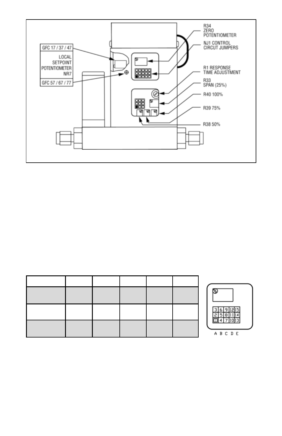
FIGURE 2-2, POTENTIOMETER AND JUMPER LOCATIONS
2.2.1
Valve Control Configuration
There are three basic valve control options.
(a) LOCAL or REMOTE control.
(b) 0 to 5 VDC or 4 to 20 mA setpoint signal -
*Note: this only applies for the REMOTE control configuration;
(c) 2% cutoff active or not active. Note: 2% cutoff not available for GFC 57/67/77.
When active, the 2% cutoff will shut off the power to the valve when a setpoint of
less than 2% of the full scale flow range is set. Figure 2-2 shows the jumper con-
figurations for the three basic valve control options.
The factory default jumper settings are: LOCAL control, 2% cutoff off, and 0 to 5 VDC.
4
FIGURE 2-3, VALVE CONTROL CONFIGURATION JUMPERS
2.2.2
Remote LCD Readouts
GFC Mass Flow Controllers are available with optional remote reading LCD dis-
plays supplied with a three foot long wire to accommodate most applications. This
configuration includes the upper block element which serves as the LCD readout
mounting. Special lengths of remote extension wiring (up to 9.5 feet [3 meters])
are available on request.
FUNCTION
NJ1A
NJ1B
NJ1C
NJ1D
NJ1E
0 to 5 VDC
4 to 20 mA
2 - 3
1 - 2
5 - 6
4 - 5
8 - 9
7 - 8
local
remote
11 - 12
10 - 11
2% cutoff on
2% cutoff off
13 - 14
14 - 15