Aalborg GFC User Manual
Page 13
GFC 17/37/47 CAUTION
CAUTION: If the valve is left in the AUTO (control) or OPEN (PURGE)
mode for an extended period of time, it may become warm or even hot
to the touch. Use care in avoiding direct contact with the valve during
operation.
Do not run GFC 17/37/47 models for extended periods of time with the valve in
AUTO or PURGE mode without the flow of gas through the transducer. Doing so
may result in up to 2% f.s. shift in calibration.
ƽ
9
5.
OPERATING INSTRUCTIONS
5.1
Preparation and Warm Up
It is assumed that the Mass Flow Controller has been correctly installed and thor-
oughly leak tested as described in section (2). Shut the flow source OFF. Apply
power to the unit via the 15-pin “D” connector. Use a power supply that is between
+12 and +15 VDC with at least 800 mA current capacity (or optionally, for models
GFC17/37/47 only, +24 VDC 650 mA). Allow the Mass Flow Controller to warm-
up for at least 15 minutes.
During initial powering of the GFC transducer, the flow output signal will be indi-
cating a higher than usual output. This is indication that the GFC transducer has
not yet attained its minimum operating temperature. This condition will automat-
ically cancel within a few minutes and the transducer should eventually zero.
If after the 15 minutes warm-up period, the display still indicates a reading of less
than ± 3.0 % of F.S., readjust the ZERO potentiometer [R34] through the access
window. Before zero adjustment temporarily disconnect the gas source, to ensure
that no seepage or leak occurs in to the meter.
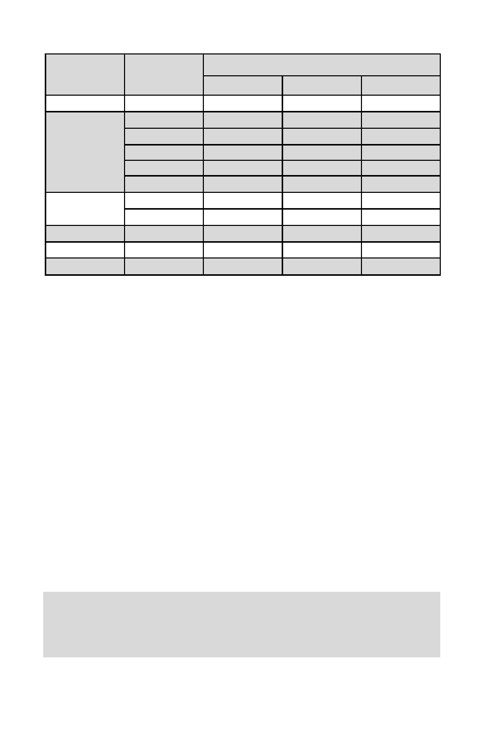
TABLE IV PRESSURE DROPS
MODEL
FLOW RATE
[liters/min]
MAXIMUM PRESSURE DROP
[mm H2O]
[psid]
[mbar]
GFC 17
UP to 10
720
1.06
75
GFC 37
15
2630
3.87
266
20
1360
2.00
138
30
2380
3.50
241
40
3740
5.50
379
50
5440
8.00
551
GFC 47
60
7480
11.00
758
100
12850
18.89
1302
GFC 57
200
7031
10.00
690
GFC 67
500
8437
12.00
827
GFC 77
1000
10547
15.00
1034