Aalborg GFC User Manual
Page 22
7.2.5
Connections and Initial Warm Up
Connect the multimeter to output pins [1] and [2] for 0 to 5 VDC (or pins [9] and
[14] for 4 to 20 mA) of the 15-pin “D” connector - (see Figure 2-1).
If calibration to a new flow range or different gas is being performed, it may be
necessary to remove any jumpers at J1A, J1B, and J1C before beginning lin-
earizing procedure.
Power up the Mass Flow Controller for at least 30 minutes prior to commencing
the calibration procedure.
7.2.6
ZERO Adjustment
Shut off the flow of gas into the Mass Flow Controller. To ensure that no seepage
or leak occurs into the meter, it is good practice to temporarily disconnect the gas
source.
Using the multimeter and the insulated screwdriver, adjust the ZERO poten-
tiometer [R34] through the access window for 0 VDC (or 4 mA respectively) at
zero flow.
7.2.7
25% Flow Adjustment
Reconnect the gas source. Using the flow regulator, adjust the flow rate to 25% of
full scale flow. Check the flow rate indicated against the flow calibrator. Adjust the
setting for potentiometer [R33] by using the insulated screwdriver through the
access window, until the output of the flow meter reads 1.25VDC ±63mV (or 8mA
±0.25mA).
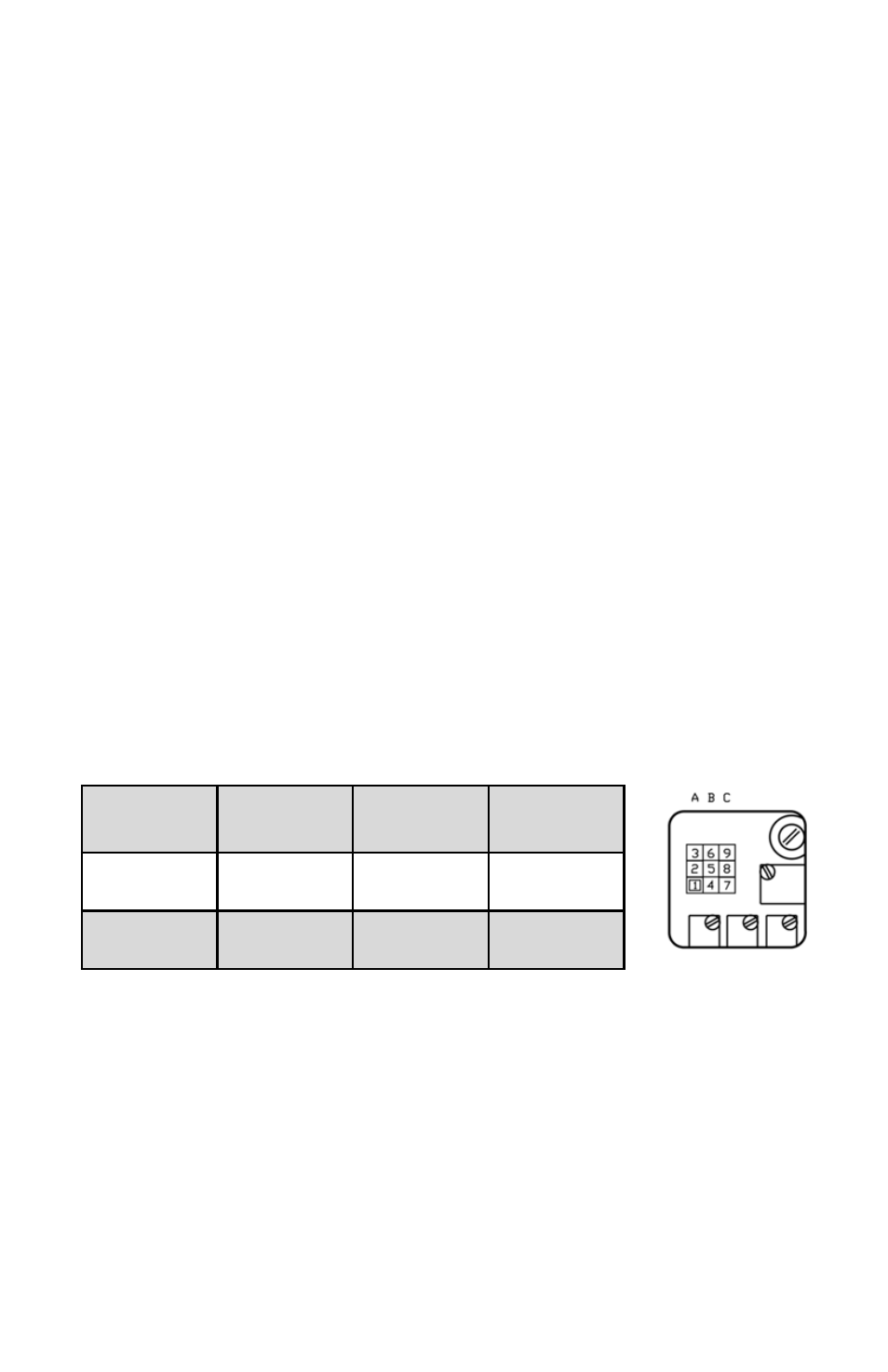
FIGURE 7-2 CALIBRATION POTENTIOMETER AND JUMPERS
7.2.8
50% Flow Adjustment
Using the flow regulator, increase the flow rate to 50% of full scale flow. Check the
flow rate indicated against the flow calibrator. The output of the flow meter should
read 2.50VDC ±63mV (or 12mA ±0.25mA). If the reading is outside of that range,
place the jumper at [J1A] as appropriate to increase or decrease the signal. Adjust
the setting for potentiometer [R38] by using the insulated screwdriver through the
access window, until reading is within specification.
18
LINEARIZER
FUNCTION
J1A (50%)
J1B (75%)
J1C (100%)
Decrease
1 - 2
4 - 5
7 - 8
Increase
2 - 3
5 - 6
8 - 9