Part 1 installation, Viii initial start- up /adjustment on-off burners – Midco Unipower MPG Series User Manual
Page 9
___________________________
1) Check the gas piping for leaks. If a leak is detected it should be located with a
soap suds test and repaired.
2) Make sure that the burner main and pilot gas lines are both completely purged of air.
Don’t purge into the combustion chamber. Purge outside the building.
3) Make sure the burner power switch is off, manual valves of main gas and pilot gas
are closed, and motor is free to rotate.
4) Make the proper settings on all limit controls and set controller to call for heat.
5) Set air shutter to the correct position according to Table 6 and tighten in place.
6) Energize Power On-Off switch, and allow motor to run through the pre-purge of 30
seconds and the pilot ignition cycle. Check the blower wheel for proper rotation.
Viewing from blower inlet side, rotation should be counter-clockwise. With no pilot
gas, the flame safeguard will lock out, stopping the motor.
7) Wait one minute, reset the flame safeguard and open the pilot manual valve with
main manual valve still closed. When pre-purge period of 30 seconds has been
completed the pilot solenoid valve and spark generator will be energized. The pilot
should light and the flame rod senses pilot flame. Adjust the pilot gas pressure to
reach a strong and stable pilot flame according to Table 8. Test for ignition and
stability of pilot several times.
8) Turn off Power On-Off switch. Open Main Manual Shut-off Valve half way.
9) Find the required main gas manifold pressure from the Table 6. Use a Digital Gas
Manometer to measure the main gas manifold pressure.
10) Turn on Power On-Off switch. The burner will start and go through the 30 second
pre-purge period and you should have pilot ignition and then the Main flame should
light
11) Slowly open the Main Manual Shut-off Valve and adjust the gas pressure regulator on
the Main Gas Combination Valve, until the main gas manifold pressure reaches the
required value as shown in Table 6 and the Main Manual Shut-off Valve is wide open.
12) Check the emissions in the flue with a Gas Analyzer, adjust the Air Shutter until
the O
2
level of flue gas is approximately 3.5-4.5 %.
13) Cycle the burner on and off several times and check for Pilot ignition, Main gas
ignition, main gas manifold pressure and O
2
, CO
2
, and CO readings.
For Hi-Low and Full Mod startup instructions see section XVI
Part 1 Installation
9
VIII
Initial Start-
up /Adjustment
On-Off Burners
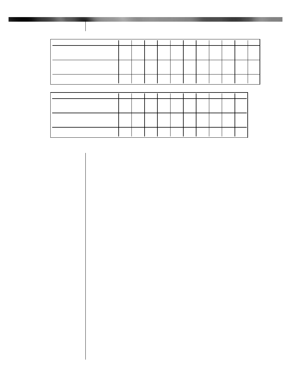
MPG 1.5 (2 Stage and Full Modulation) Gas Flow & Air Shutter Setting
Firing Rate
(MBH/Hr)
*
500
600
700
800
900
1000 1100 1200 1300 1400 1500
Natural gas pressure drop
between 2nd valve and main
0.06
0.09
0.12
0.16
0.20
0.24
0.30
0.35
0.41
0.48
0.55
gas flow control valve, " W.C. *
Propane gas pressure drop
between 2nd valve and main
0.03
0.05
0.07
0.09
0.11
0.13
0.16
0.19
0.23
0.26
0.30
gas flow control valve, " W.C. *
Air shutter position
0.0
0.0
0.0
0.2
0.3
0.5
0.8
1.4
2.3
4.0
6.8
MPG 2.5 (2 Stage and Full Modulation) Gas Flow & Air Shutter Setting
Firing Rate
(MBH/Hr)
*
850
900
1100 1300 1500 1700 1900 2100 2300 2500
Natural gas pressure drop
between 2nd valve and main
0.06
0.06
0.10
0.14
0.18
0.23
0.29
0.35
0.42
0.50
gas flow control valve, " W.C. *
Propane gas pressure drop
between 2nd valve and main
0.03
0.04
0.05
0.06
0.10
0.13
0.16
0.20
0.24
0.28
gas flow control valve, " W.C. *
Air shutter position
0.0
0.0
0.2
0.4
0.7
1.1
1.6
2.0
2.5
3.5
* 1 MBH=1,000 BTU/HR
** Based on zero chamber pressure at sea level (Chamber pressure can be measured at pilot gas pressure tap with pilot gas off
Table 7: Manifold Gas Pressure and Air Shutter Settings