Part 1 installation – Midco Unipower MPG Series User Manual
Page 6
6
be of the listed type and installed and adjusted by a qualified service technician in accordance
with the manufacturer's instructions.
___________________________
Electrical installation must be made in accordance with the United States to National Electric
Code, ANSI/NFPA No.70-latest edition or Canadian Electrical Code, Part 1, CSA Standard
C22.1. and applicable local code. If the burner is a part of a gas utilization equipment system,
check the wiring diagram as supplied by the manufacturer.
The burner when installed, must be wired and grounded in accordance with local codes or in
the absence of local codes, with the National Electric Code ANSI/NFPA No. 70-latest edition.
In Canada, refer to CSA Standard C22.1, "Canadian Electrical Code Part 1".
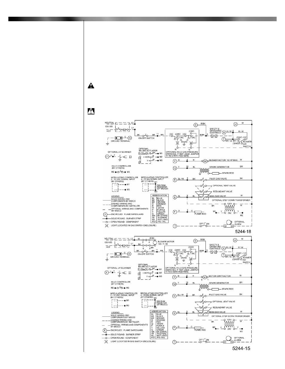
CAUTION: Refer to the separate wiring diagram included with each burner.
When wiring, be sure that the electrical power take-off is connected to a permanently live
circuit and use multiple 14 gage copper wire conductors. Provide a fused disconnect switch in the
burner circuit. Each installation must include a limit control to guard against excess temperature
or steam pressure. Steam or vapor systems will require a low water cut-off.
WARNING: Wiring shown is for standard burners. Consult the factory for specific
wiring and have the Bill of Material Number ready when calling.
___________________________
Part 1 Installation
V
Electrical
Figure 7A: Wiring Diagram for MPG 1.5G - 120 V
Figure 7B: Wiring Diagram for MPG 2.5G - 120V