Part 1 installation, Vii main gas input selection vi piping continued – Midco Unipower MPG Series User Manual
Page 8
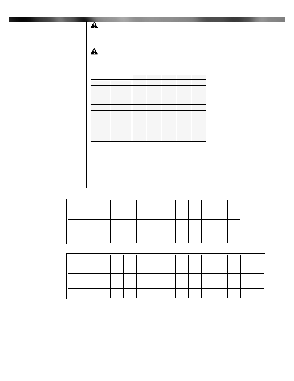
CAUTION: Do not exceed maximum rated capacity of burner model-See Tables 1 & 2.
Before gas is introduced to the system, a check must be made to see that there are no open
fittings and to make sure the burner main and pilot manual valves are closed. After checking
above, purge the gas line up to the burner inlet. Purging the air from the gas supply line at this
step will expedite the first light-off.
CAUTION: Purge outside the building. Do not purge into the gas utilization equipment
combustion chamber.
___________________________
Burners are approved for use with NATURAL gas or PROPANE gas and should be used only
with the gas specified on the rating plate.
The gas input should be set at the heating rate determined by the building heat loss and/or
heating plant survey, but not exceeding the rated maximum input of the gas utilization equipment.
8
Part 1 Installation
VII
Main Gas
Input Selection
VI
Piping
Continued
20
730
1150
1100
1730
2100
2500
2500
2500
2500
2500
60
400
630
610
960
1150
1800
1850
2500
2500
2500
100
300
480
460
725
870
1370
1400
2200
2500
2500
40
500
785
760
1200
1450
2280
2300
2500
2500
2500
Pipe
Size
1 1/4
1 1/4
1 1/2
1 1/2
2
2
2 1/2
2 1/2
3
3
Natural
Propane
Natural
Propane
Natural
Propane
Natural
Propane
Natural
Propane
200
330
320
500
610
960
980
1550
1700
2500
Approximate Capacity -MBH
Pipe Length
Type
of Gas
Capacities shown are for a
total pressure drop of
0.3"W.C. For 0.5"W.C.
pressure drop, multiply
capacity shown by 1.3 .
Propane capacities shown
are for a total pressure drop
of 0.5” W.C. For higher
permissible pressure drops,
consult your gas supplier.
Source: Gas Engineers
Handbook - 1974
Table 5: Schedule 40
PT Pipe-Capacity Chart
MPG 1.5 (On-Off) Gas Flow & Air Shutter Setting
Firing Rate
(MBH/Hr)
* 500
700
800
900
1000 1100 1200 1300 1400 1500
Natural gas
manifold pressure
0.13
0.26
0.34
0.43
0.53
0.65
0.77
0.90
1.05
1.20
" W.C. **
Propane gas
manifold pressure
0.08
0.15
0.20
0.25
0.31
0.38
0.45
0.53
0.61
0.70
" W.C. **
Air shutter
position 0.0
0.0
0.2
0.3
0.5
0.8
1.4
2.3
4.0
6.8
MPG 2.5 (On-Off) Gas Flow & Air Shutter Setting
Firing Rate
(MBH/Hr)
* 850
1500 1600 1700 1800 1900 2000 2100 2200 2300 2400 2500
Natural gas
manifold pressure
0.09
0.29
0.33
0.37
0.41
0.46
0.51
0.56
0.62
0.68
0.74
0.80
" W.C. **
Propane gas
manifold pressure
0.06
0.18
0.20
0.23
0.26
0.29
0.32
0.35
0.39
0.42
0.46
.050
" W.C. **
Air shutter
position 0.0
0.7
0.9
1.1
1.3
1.6
1.8
2.0
2.2
2.5
2.9
3.5
*
1 MBH=1,000 BTU/HR
**
Based on zero chamber pressure at sea level (Chamber pressure can be measured at pilot gas pressure tap with pilot gas off
Table 6: Manifold Gas Pressure and Air Shutter Settings