Videotec DCTEL User Manual
Page 34
Page 10
MNVCDCBD01_0442
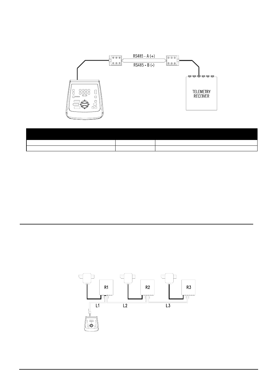
The DCTEL keyboard can be connected directly, using the RJ11 plug telephone cable supplied, to DTRX3 type
receivers to test correct operation of the appliances in the laboratory.
Over greater distances, RJ jack wall boxes can be used and connected by bipolar cable according to the
following diagram:
DCTEL (RJ11 A o B)
telemetry line
Receiver
DTRX3 / DTMRX1 / MICRODEC485 / DTRXDC
TX-485A White (+)
-------
Blue RX-485A
TX-485B Yellow (-)
-------
Black RX-485B
Depending on the type of configuration used for the system, it is necessary to proceed with insertion/removal of
the load (termination resistance) on the RS485 line for the telemetry line. To set the load just set DIP1 on the
back of the keyboard as follows:
• DIP1 ON: Load inserted.
• DIP1 OFF: No load.
The following are three examples of possible connections for the telemetry line:
• Point-to-point
connection
• Multi-point
connection
• Mixed connection (point-to-point/multi-point)
6.4.1 Connecting a keyboard with one or more receivers in cascade (point-to-point connection)
This type of connection allows the use of a single keyboard to control one or more receivers arranged in
cascade (point-to-point type connection). The DCTEL keyboard should have the termination resistance inserted
(DIP1 ON) in the RS485 line. Each receiver in turn should also have the termination resistance of the RS485
line inserted. A maximum of 16 receivers can be controlled in cascade. Each receiver should obviously have a
different address from all the others (the receiver address is between 1 and 16). Configure the receivers with
the RS485 communication protocol and with the same baud rate as the DCTEL keyboard.