Videotec DTRXDC User Manual
Page 24
Page. 4
DTRXDC 2900
Installation examples
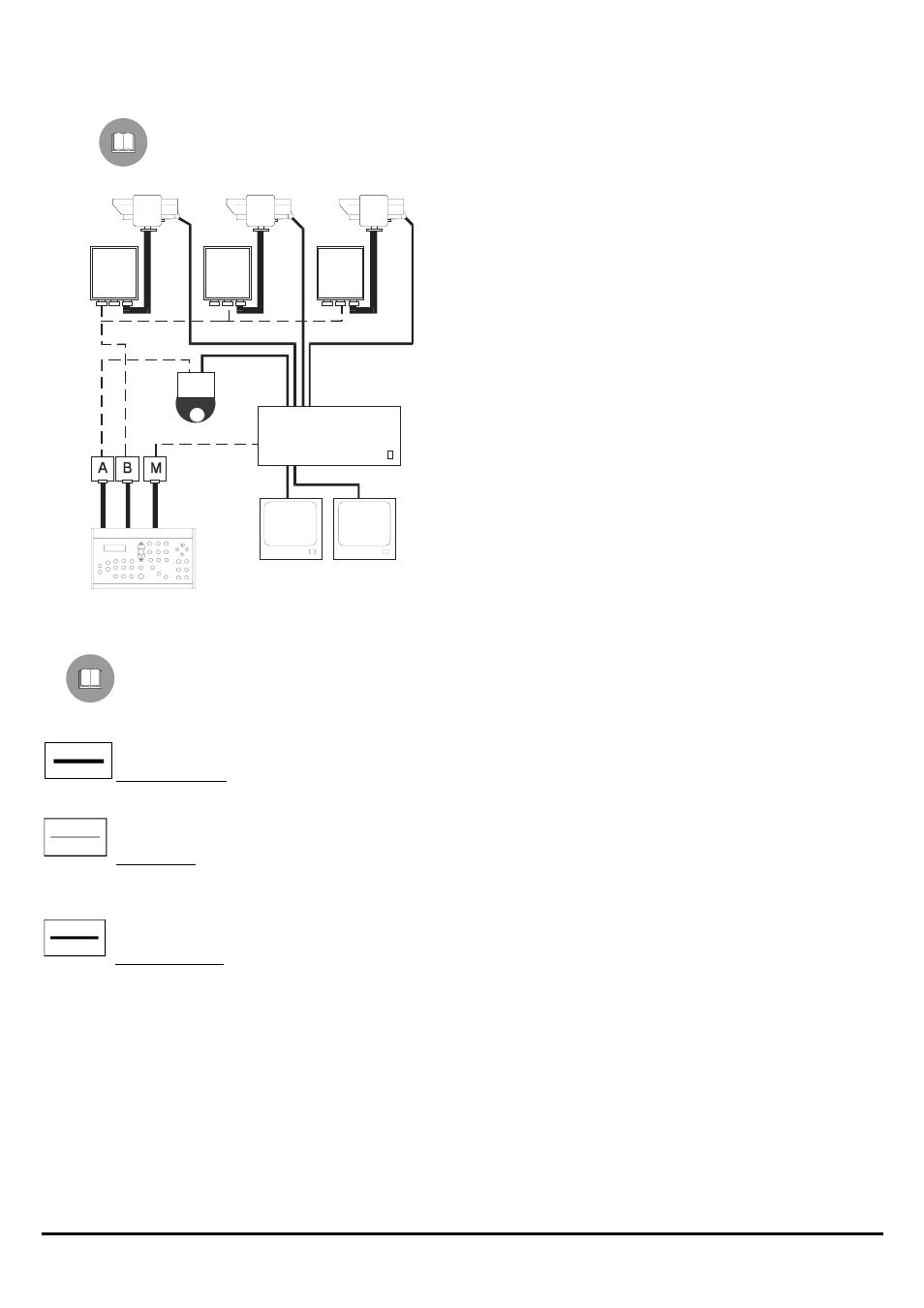
Installation managed by a single operator, with control of video switching and of a series of pan & tilts.
DEVICES
Control keyboard section:
• 1 keyboard DCS3
Video section:
• 2
monitor
• 3 cameras (+ 1 in the receiver OEM)
• 1 SW328 video matrix
Telemetry section:
• 3 DTRXDC receivers
• 3 PTH355P Pan & Tilt
• 1 receiver OEM (with camera included)
Cables
In the diagrams given as examples, different types of lines have been used to show cables with different
functions:
telephone cable:
1.5 m, supplied with the keyboard.
video cable:
RG 59 coaxial cable or equivalent.
For long distances we advise a video transmission system on a twisted pair.
multipolar cable:
Determine the final number of cables, using the following indications:
4 wires for pan & tilt movements (24 V
=
): right, left, up, down, autopan
6 wires for controlling lens, with polarity inversion (zoom, focus, iris)
4 wires for controlling lens with common wire (zoom, focus, iris)
7 wires for managing preset: 5 connected to reference potentiometers, +5 V
=
and earth
2 wires for each auxiliary used
3 wires for power supply cable
Note: we advise the use of different multipolar cables for the different functions.
Minimum section advisable:
− 0.56 mm.² (AWG 20) for connections in high tension.
− 0.34 mm.² (AWG 22) for connections in low tension.
− 0,75 mm.² (AWG 18) CENELEC H05VV-F for DTRXDC power supply wires.
SW328
DCS3
DTRXDC
DTRXDC
DTRXDC