Videotec CBZ User Manual
Page 22
Page
6
MNVCCBZ_0828
Connectors and connections
The installation must be carried out only by qualified technical staff: an improper connection of the peripheral
units may cause the keyboard to be isolated from the rest of the system.
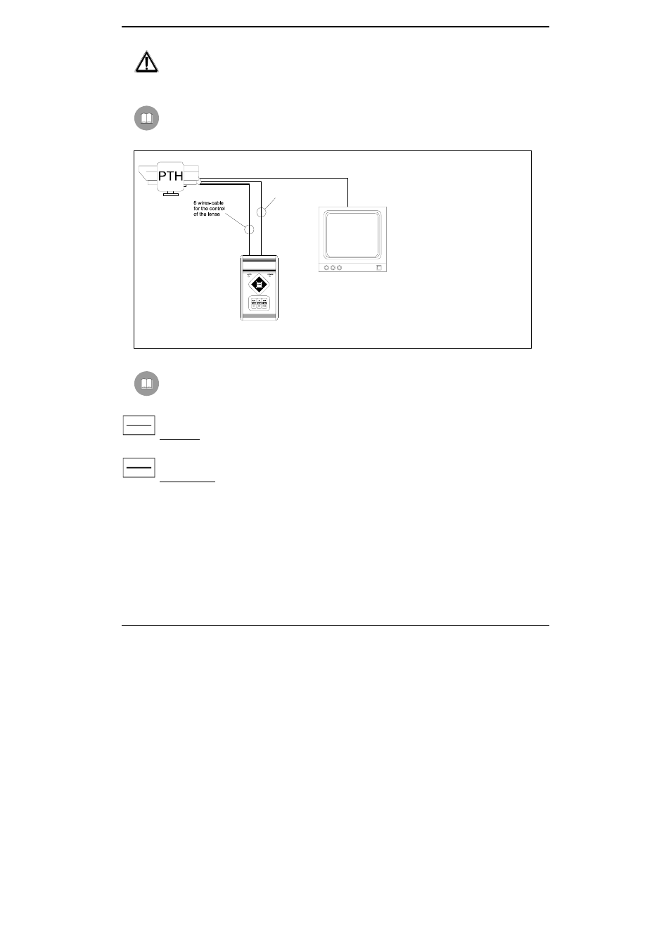
Installation example
Installation controlled by one operator with one monitor: the operator controls one pan & tilt motor and the
camera functions FOCUS, ZOOM, IRIS:
MATERIAL USED
Control keyboard:
• 1 control keyboard
CBZ220/CBZ24
Video handling:
• 1
monitor
Telemetry handling:
• 1 pan & tilt motor
• 1 motorized zoom lens
Cables
Different types of stroke have been used in the previous examples, in order to indicate cables with different
functions:
video cable:
RG 59 coaxial cable or equivalent cable
multipolar cable:
each control function of the positioning device is activated /deactivated by a relay positioned inside the receiver.
Fix the final numbers of wires according to the following directions:
7 wires for the motion of the positioning device: right, left, up, down, autopan, common, ground
6 wires for the control of polarity reversal lenses (zoom, focus, iris)
4 wires for the control of common wire lenses (zoom, focus, iris)
2 wires for the auxiliary device
Note: We recommend the use of different multipolar cables for high tension and low tension functions.
Minimum section area recommended: 0.56 mm.² (AWG 20) for high tension wires (positioning device)
0.34
mm.²
(AWG
22)
for
low
tension wires (lens, auxiliary device)
CBZ220/CBZ24
7 wires-cable for the
control of the P&T head