4 connection of the secondary connector board, 1 board description, 2 connection of the alarm inputs – Videotec ULISSE COMPACT HD User Manual
Page 13
Instruc
tions manual - English - EN
13
MNVCUCHD_1405_EN
6.1.4 Connection of the secondary
connector board
6.1.4.1 Board description
BOARD DESCRIPTION
Connector
Function
J1
Ethernet Connector
J4
Alarm and relay connector
Tab. 3
J4
J1
Fig. 10 Alarms, relay and HD IP video output board.
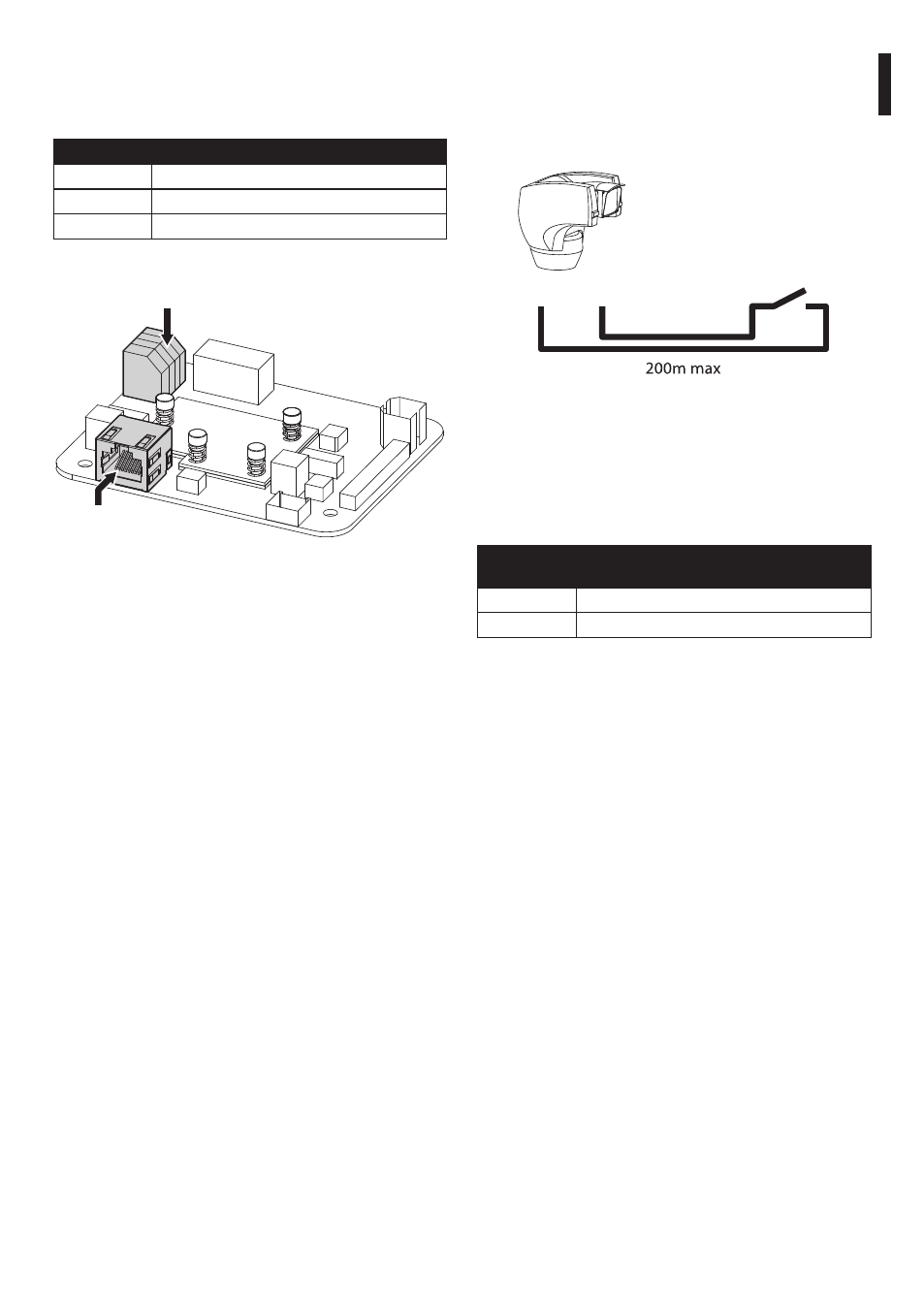
6.1.4.2 Connection of the alarm inputs
In case of free contact alarm make the connection as
shown in the figure.
The alarm contacts are present on the connector J4.
A
G
Dry contact
Fig. 11
The clean contact alarm can be NO (normally open)
or NC (normally closed).
For further details on configuring and using the
alarms, refer to the related chapter (8.2.10 Digital I/O,
page 24).
CONNECTION OF THE ALARM INPUTS, OF THE
TWILIGHT SWITCH AND OF THE RELAYS
Terminal
Description
A, G
Self-powered alarm input referred to G
Tab. 4
All alarms have an approximate reach of 200m, which
can be obtained using an unshielded cable with a
minimum section of 0.25mm² (AWG 24).