Connecting wires to terminals – Kenwood DPX305U User Manual
Page 10
10 | Quick Start Guide
P.CONT
REMOTE CONT
REMOTE INPUT
STEERING WHEEL
ANT.
CONT
MUTE
L
R
L
R
1
2
3
4
5
6
7
8
1
2
3
4
5
6
7
8
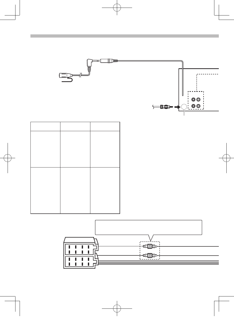
Connecting Wires to Terminals
FM/AM antenna input (JASO)
Antenna Cord
⁄
See
Red (Ignition wire)
Yellow (Battery wire)
Red (A–7 Pin)
Yellow (A–4 Pin)
Connector A
Connector B
Connector Function Guide
Pin Numbers for
ISO Connectors
Cable Colour
Functions
External Power
Connector
A-4
Yellow
Battery
A-5
Blue/White
Power Control
A-6
Orange/White
Dimmer
A-7
Red
Ignition (ACC)
A-8
Black
Earth (Ground)
Connection
Speaker
Connector
B-1
Purple
Rear Right (+)
B-2
Purple/Black
Rear Right (–)
B-3
Gray
Front Right (+)
B-4
Gray/Black
Front Right (–)
B-5
White
Front Left (+)
B-6
White/Black
Front Left (–)
B-7
Green
Rear Left (+)
B-8
Green/Black
Rear Left (–)
Microphone
(Accessory4)
Microphone input (DPX405BT only)
B59-2160-00_00_13-2DIN_QSG_E_en.indd 10
12/11/21 15:04