Fa c p, Facp dsm – Notifier ET Series User Manual
Page 3
dn-2225:a1 • 2/9/10 — Page 3 of 4
WIRING DIAGRAMS
+
+
+
+
–
–
–
–
–
–
+
+
F
A
C
P
ET
ET
ET
ET
ET
ET
DSM #1
DSM #2
DSM #3
+
–
+
–
+
–
Strobe NAC Circuit
Strobe NAC Circuit
Strobe NAC Circuit
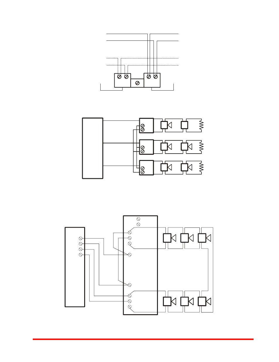
DSM Interconnecting wiring shown. Maximum of 20.
FACP
DSM
SYNC
+
SYNC
–
+
OUT 1
+
IN 1
MINUS 1
+
AUDIBLE
+
IN 2
MINUS 2
–
AUDIBLE
Strobe NAC Circuit
OUT
ET
ET
ET
ET
ET
ET
ET
ET
ET
ET
Strobe NAC Circuit
RETURN
+
OUT 2
Series ET Speaker and Strobe Operate Independently
(Non-Sync or Sync)
Series ET Speaker Strobes Synchronized
with DSM Module Single Class “A”
Series ET Speaker Strobe Appliances Synchronized
with DSM Module Single Class “A”
NOTE: Figure shows
interconnection to
strobe through sync
module. Speaker
portion requires 2
separate conductors to
FACP.
Strobe
Speaker
222
5bd1.
wmf
2
225b
d2.wmf
2225b
d3.wm
f
See also other documents in the category Notifier Safety:
- 411UDAC Rev 2 Fire Alarm Communicator (4 pages)
- FAPT-851 (2 pages)
- FCM (2 pages)
- FCO-851 (2 pages)
- FMM (4 pages)
- FSB-200(A)/-200S(A) (4 pages)
- FSC-851 (2 pages)
- FSI-851 (2 pages)
- FSL-751 (2 pages)
- FSP-851 (2 pages)
- FST-851 (2 pages)
- FTM-1(A) (2 pages)
- ISO-X (2 pages)
- N100-ISO (2 pages)
- NBG-12LX (2 pages)
- NC-100(R) (2 pages)
- NH-100 (2 pages)
- NI-100(A) (2 pages)
- NMM (4 pages)
- NOT-BG12LX (2 pages)
- NP-100(T)(A) (2 pages)
- XAS-1-US (2 pages)
- XP10-M 10 (2 pages)
- ND-100R (4 pages)
- 1451 2-Wire (4 pages)
- 302 Series (10 pages)
- 30-2021-24 (4 pages)
- 30-2056B (4 pages)
- 5451 (2 pages)
- 5600 Series (2 pages)
- 8100(A) (2 pages)
- B401BH (2 pages)
- BEAM1224(S) (2 pages)
- BNG Series (2 pages)
- FD Series Single UV (4 pages)
- FD Series Triple IR (4 pages)
- FD Series UV/IR Flame Detector (4 pages)
- I3 Series (2 pages)
- MPS-950 Series (2 pages)
- NBG-12 Series (2 pages)
- NBG-23LR(A) (2 pages)
- NFM-950B/KB (1 page)
- PIBV2 (2 pages)
- AS Series (4 pages)
- E Series (4 pages)