Maintenance, Checkout procedure, Installation – Notifier 30-2056B User Manual
Page 3
DN-5517:B1 • 7/13/11 — Page 3 of 4
Maintenance
To assure maximum detector sensitivity, the lens must be
kept free of dirt or other contaminating film.
The detector should be tested regularly. If it fails a test, clean
the lens and test again. If the detector fails again, it should be
removed and replaced. The defective detector should be sent
to the factory for repairs.
NOTE: Remove power to the detector before cleaning the lens or
disconnecting external wiring.
Checkout Procedure
A checkout of the system using the oi feature, a flame, or
other flickering IR source should be performed on a regularly
scheduled basis to ensure that the system is operating prop-
erly. The period between checkouts will depend on the levels
of potential hazard involved in the environmental conditions
encountered. In general, the more frequent the checkouts,
the greater the reliability of the system.
Any extinguishing equipment connected to the system must
be disabled when the system is tested to prevent unwanted
actuation of this equipment. To test the system, point a test
lamp at each unit or activate the remote test feature for five to
ten seconds. Alarm response indicates that the viewing win-
dow is clean and that all electronic circuitry is operational.
Lack of response may indicate reduced sensitivity due to
contamination on the viewing window, a damaged sensor, or
electronic circuitry problems.
Installation
The installer should provide a 3/4-inch conduit to the appro-
priate point where the detector is to be located. This conduit
must be grounded. All wiring cables to the detectors must be
shielded and the shields must be grounded. The use of con-
duit seals is recommended.
T
o prevent ignition of a hazardous atmosphere, do not
remove the cover while power is applied to the detector.
1. Provide a shielded wiring cable (16 to 22 AWG recom-
mended) with a minimum of 6 inches service loop at the junc-
tion box.
NOTE: Be certain that all wiring complies with the local wiring
codes. If necessary, consult a qualified official.
2. Connect the external wiring to the detector.
3. Place the cover on the detector. Be sure the O-ring is in
place and that no wires are trapped.
4. To ensure proper coverage of the surveillance area, ori-
ent the detector so that the lens faces the center of the area
to be protected.
5. Clean the oi ring and sensor window with a clean lint-
free cloth. Wet with alcohol only.
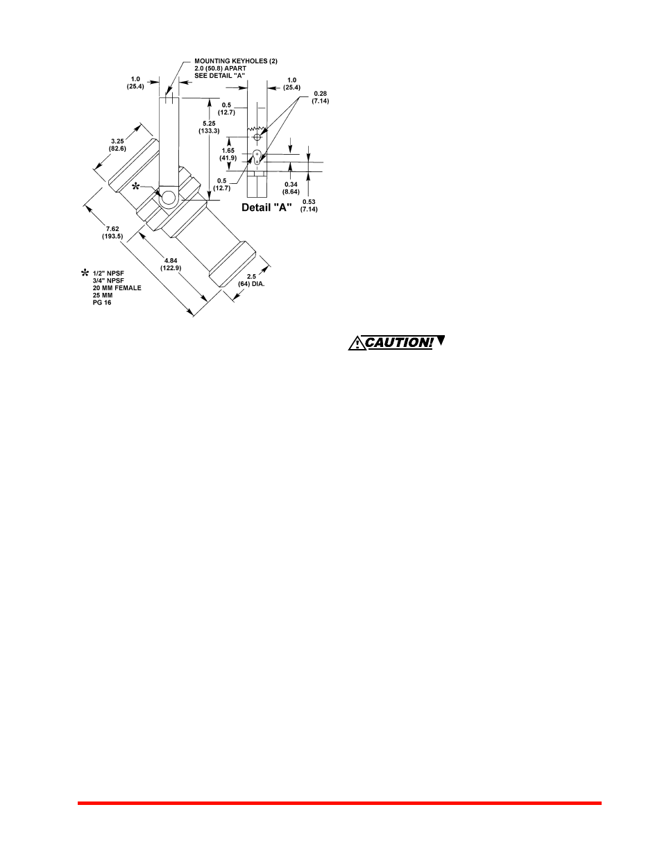
5517f3.tif
Figure 3
Dimensions in Inches (mm)