Cone of vision, Theory of operation, Specifications – Notifier 30-2056B User Manual
Page 2
Page 2 of 4 — DN-5517:B1 • 7/13/11
test switch, usually located at the control panel. This actuates
an integral IR radiation source that is mounted inside the
detector, resulting in the simulation of a flickering fire. Upon
detection of the simulated fire, the detector latches into an
alarm condition to indicate that it is operating correctly. The
detector can then be reset by interrupting power to the unit
for a minimum of 0.3 second. The detector will fail remote
testing if 50% of the detection range is lost.
The LED is illuminated during an alarm condition to serve as
an integral visual alarm indicator.
IMPORTANT: Proof of successful remote test is activa-
tion of alarm relay.
Cone of Vision
The detector has a nominal 80 degree cone of vision. How-
ever, the detector can be rotated up to 360° so that the area
to be protected is within its cone of vision. Proper aiming and
adequate coverage is recommended to ensure hazardous
area protection. See Figure 2 below.
Theory of Operation
The electromagnetic emission of a hydrocarbon fire is char-
acterized by a strong band in the 4.2 to 4.7 micron range.
This band, known as the CO
2
spike, is caused by the emis-
sion of energy generated by excited CO
2
molecules. Since
this is the dominant feature of the spectral emission for
hydrocarbon fires, the IR sensor is designed to respond with
peak sensitivity to radiant energy at the 4.45 micron range.
The detection cell is a specially developed pyro-electric cell
with an integral optical filter window, which restricts incoming
light to the wavelength band 4.2 to 4.7 microns (the CO
2
spike). The detection cell responds by generating a signal
that is proportional to the radiation being detected.
The electronic circuitry that processes the signal from the
detection cell checks for flicker response, ignoring signals
from spurious light sources. The flicker rate and count
requirements are factory set for levels characteristic of a
hydrocarbon fire. A flickering signal that exceeds the preset
alarm threshold will result in actuation of the alarm relay.
Specifications
Operating voltage: 18 to 32 VDC, with maximum ripple 0.5
vpp at 60 to 120 Hz.
Operating current: Standby: 1 watt. Alarm: 3.5 watts maxi-
mum.
Relay contact rating: Alarm and Fault Relays have Form-C
contacts and are rated for 2.0 at 30 VDC.
Spectral sensitivity range: 4.2 to 4.7 microns.
Response time: Detector responds to a 1 foot-square gaso-
line fire (at zero axis to detector) in less than 6 seconds at 50
feet.
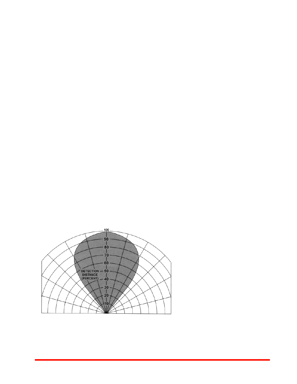
Cone of vision: 80 degrees nominal with sensitivity to 70%
at 40 ± 2 degrees of zero axis. Figure 2 shows cone vision of
typical sensor.
Temperature range: Operating: –40°F to 167°F (–40°C to
75°C). Storage: –67°F to 185°F (–55°C to 85°C).
Dimensions: See Figure 3.
Enclosure: Explosion-proof and watertight, anodized alumi-
num. Explosion-proof: Class 1, Div. 1, Groups C, D. Class II
Div. 1, Groups E,F,G. Watertight: NEMA 4. Conduit fitting: 3/4
inch NPT (Female).
Shock and vibration: meets MIL STD 810C vibration.
0°
15°
15°
30°
45°
30°
45°
Figure 2
Cone of Vision of Detector
100% represents the maximum
detection distance for a given fire.
The sensitivity increases as
the angle of incidence decreases.
5517f2.tif