Dake Model Zip 28 User Manual
Page 10
10
With the blade being held in the guides, loop the blade over the drive wheel and front idle
wheels. Apply a slight amount of tension to the blade with the blade tensioning handle,
enough to hold the blade onto the wheels. Check that the blade is still fully in the guides
and push the blade up against the back lips of the wheels. Tighten blade tensioning
handle until it dead heads the preset bolt. (Paragraph C in section2)
NOTE: Before installing the blade check the blade because at times the blade will
reverse it self while uncoiling, make sure teeth are facing the rear of the machine
or in the direction the blade travels. If blade is reversed carefully twist the blade to
reverse the teeth direction.
6. Replace the blade guard; make adjustments so it does not rub on the blade.
7. Replace rear blade cover. Make sure interlock switch in engaged. (Paragraph G in
section 2)
8. Restore power to the machine and jog the blade a few times to make sure the blade is
seated into the guides.
6. Calibrating blade guides and tensioning preset bolt for different size blades.
NOTE: It is recommended that the same size of blade be used as originally equipped. Dake is
not responsible for any of the following changes that may be required for blades of different
specifications.
1. The machine is calibrated for a bi-metal blade that is 97 ½” long, 1” wide and 0.035 thick.
Never use blades that are wider than 1” or narrower than 1”. Damage may occur to guides
and blade.
If a blade is used that is either longer, shorter or of a different thickness re-calibration may
be necessary to the preset bolt or blade guides.
2. Preset tension bolt can be adjusted inward or outward for shorter or longer blades. To
calibrate the bolt should be screw inward to allow installation on the new blade. With the
blade installed is should be tensioned according to the manufactures specifications using
a tension gauge. With proper tension applied adjust the preset bolt out until it dead heads
the tensioning handle. Lock in place with the jam nut. (Paragraph C in section 2)
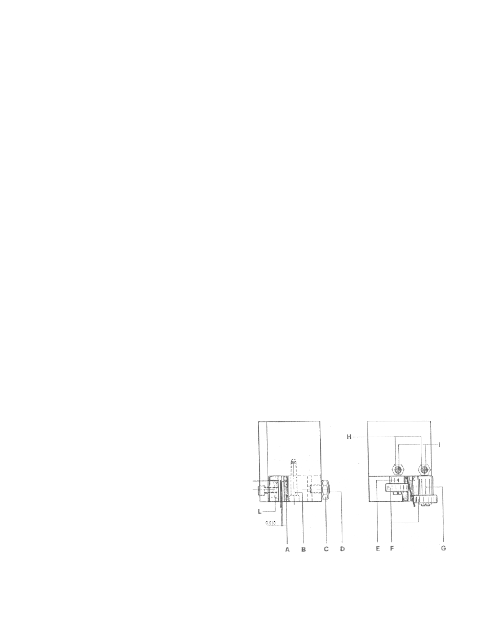
3. For a blade of a different thickness, thinner or thicker the guide pads may require
adjustment.
Loosen nut C, screw B and set screw D
Widening the distance between pads.
Loosen nuts H, and set screws I and
Rotate the eccentric pins E-G to widen
Clearance between bearings F.
Mount new blade and place the blade
Against pad A, adjust set screw D until
You have approx. 0.010 – 0.015 of
Clearance to blade. Lock screw a in place
with nut C.
Rotate eccentric pins E-G until bearings have a slight drag on the blade then tighten nuts
H and set screws I. Do not place too much drag on these bearings.